diy solar

diy solar

8½kW/52kWh off-grid system assembly

TorC

Solar Enthusiast
Joined
Jan 13, 2022
Messages
514
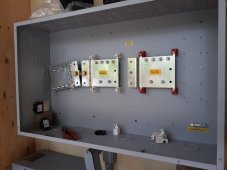
I have a Midnite BCB-1000 that I plan to put 4 Outback FM-80s, 4 DIY LFP 16S strings, and 3, perhaps in the future 4, inverter outputs (Radian 8048 & 4048).

Physically, SCCs are above the box, batteries to lower left in the next cabinet, and inverters are below.

My plan had been, given the way the 12 breaker slots are set and my configuration, to put the batteries on the lower left, inverters on lower right, and SCCs on the four uppers, two each side. This covers the entirety of available slots.

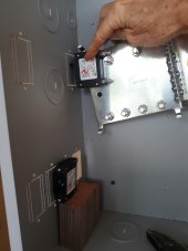
I got it with the extra busbar so I can have the shunt available (or maybe I should skip it with the JKBMS, and just rely on them?). When I go to install the busbar, I find that it runs very close to the edge, and blocks one of my breaker slots.

The place I got them from has been minimally responsive to the question. I think that's more they're overloaded entirely, as they weren't much more responsive regarding shipping quotes for the order, so I can't be too hard on them for it.

Anyone have ideas on how best to arrange my box?
 

Attachments

  • 230222_110117-bcbarrange-small.jpg
    230222_110117-bcbarrange-small.jpg
    123.5 KB · Views: 9
  • 230222_110150-bcbarrange-small.jpg
    230222_110150-bcbarrange-small.jpg
    81.1 KB · Views: 9
Last edited:
Still trying to figure out what to do, and also wondering, given the space issues, whether I should keep the shunt or not. Would rather install so I can use it, since I have it and it leaves more options open for monitoring. OTOH, I'm not even sure how detailed and with what I'll be monitoring, so it may be a moot point, but I'm wary of cables ending up too short - combination of limited space, so short is better, and back-of-envelope calculations say I'm right up against the limits of the wire I have. Home Depot doesn't stock it, and have discontinued shipping it to Hawaii.

In other news, my SCC balanced pack is nearing there. Now floating with the high cells ~3.47V, waiting for the 2A balance to catch the two low runners up. Can't complain for putting factory delivered cells together and sticking the SCC on them. Attached are a few pics of the string.  That 4/0 wire is is both custom length and terminal angle to match the location without straining. Don't mind the cutting board separators or the dangling breaker. The former are disappearing when more proper stuff shows up, and the latter is so I have a decent shutoff for balancing.

An easier question to answer: On the balance leads for this set the bus bars have a extra hole longer than I need, so in that end I drilled and tapped 6-32 for spade terminals, held in by stainless screws. Looks real nice, and I like having less going on at the busbar itself. The bus bars I have for the other two are single hole, just the right length. The square end looks like I should be able to drill just in the corner and miss my nut on top. Would this be sensible, or should I just use 1/4" hole ring terminals under the busbar nut?
 

Attachments

  • DSC_8840-small.jpg
    DSC_8840-small.jpg
    191 KB · Views: 8
  • DSC_8839-small.jpg
    DSC_8839-small.jpg
    194.6 KB · Views: 8
  • DSC_8838-small.jpg
    DSC_8838-small.jpg
    196.4 KB · Views: 8
Still wondering if anyone has thoughts on what current shunts are useful for keeping track of the system, and which aren't. It'll be 4 JKBMS B2A24S20P, 4 Outback FM-80 SCCs, and 2 Outback Radian inverters, requiring 3 inputs.

I've started moving toward setting up an RPi with the tools @BarkingSpider and @upnorthandpersonal have put together, with an eye toward seeing if I can make use of this for the parts it doesn't already handle: https://github.com/jorticus/mate-mqtt-gateway


Second question at the moment: the busbars I have for half my batteries don't have the extra length I drilled and tapped like in my above picture. Would I be better off to try to drill and tap for the balance lead just far enough from the corner to hold, or should I just go with 1/4" ring terminals on top of the busbars?

Have a query in to Midnite on my combiner box issue. It is their breakers and busbar accessory sold for the box, so maybe they have documentation I don't see on their site about the issue, but now I'm half wondering if I should just not bother with the shunt in the box.
 
Still wondering if anyone has thoughts on what current shunts are useful for keeping track of the system, and which aren't. It'll be 4 JKBMS B2A24S20P, 4 Outback FM-80 SCCs, and 2 Outback Radian inverters, requiring 3 inputs.

A Victron SmartShunt on the easy but expensive side, or something like the PZEM-017 on the cheaper end.

the busbars I have for half my batteries don't have the extra length I drilled and tapped like in my above picture. Would I be better off to try to drill and tap for the balance lead just far enough from the corner to hold, or should I just go with 1/4" ring terminals on top of the busbars?

I've always just used ring terminals on top of the bus bar terminal connections and never had issues.
 
I already have the 1kA, 100mV shunt and, in theory, all the parts for it, but not, it appears, anything to actually read it. At this point, my debate is how much effort it's worth to wire the box to include that shunt as an option to monitor batteries. Whether I actually use it is merely a related question, and I could just assume the JKBMSs feeding into that monitoring program are good enough if I can find an ~8A(?) resistive load to calibrate them against my Fluke 87V. Pre-calibration, they're kind of unreliable according to my Outback SCC, or maybe they just can't handle <1A.

Thanks for the confirmation on ring terminals. Those arrived today (ordered more than I planned to need for availability reasons), so I can get on that.
 
Well, for current monitoring, given the shunt I have, it looks like I should be able to wire this differential ADC up to my shunt and get about fifteen 78mA resolution samples per second if I use only one input for each chip on the board, or in 14 bit mode, sixty 312mA spls/s. I haven't dug into the code for the monitor at all, but I'm going to guess even a relative Python novice like me can probably figure out adding that.

Edit: Oh, now this looks very interesting: https://www.waveshare.com/18983.htm . Feed that in, and it looks like it should be able to take any shunt anyone here is likely to use, and be able to accurately measure crazy small current flow. I'm not sure how multiplexed it is, in terms of reading multiple shunts, but if I'm reading correctly, it's can read 1200 samples per second with over 18 noise free bits on a ±156mV range. On a 1kA/100mV shunt, I think that implies 6mA resolution at 1200sps. I'm not sure I know quite enough do it, but if that couldn't be turned into stupid-accurate SoC monitoring for a system I'll eat my hat.
 
Last edited:
Next problem is understanding where to put the terminal in these breakers. They just have a stud coming out of the plastic breaker case. Looks like the factory arrangement is grounding washer, nut, two flat washers, and finally another nut. See pic. Question is, where should I put the terminal lug to properly get 80A onto the post?

Got a reply from Midnite, and on consideration, decided to just move the breaker closer to the front of the box. A bit of work, but I think it came out reasonably neatly overall. There will be another like breaker in the slot next to it, but it seems I need to acquire the adapter for it.
 

Attachments

  • DSC_8842-small.jpg
    DSC_8842-small.jpg
    184.8 KB · Views: 1
  • DSC_8844-small.jpg
    DSC_8844-small.jpg
    186.9 KB · Views: 1
Back
Top