diy solar

diy solar

Alternator Charging

Axe21

New Member
Joined
Aug 11, 2022
Messages
9
I'm replacing the 2 lead acid batteries with a 12v 230ah LiFePO4 battery in our RV. Currently the lead acid batteries and "charged" while the truck is running through the 7-pin connector. When installing the new LifePRO4 do I need to discount the ability for the battery to be charged through the 7-pin connector?
.
 
This is the problem.
Some alternator not and some do have it
So a dc to dc is not make to protect your battery
Its thare to save your alternator from overheating.


I'm replacing the 2 lead acid batteries with a 12v 230ah LiFePO4 battery in our RV. Currently the lead acid batteries and "charged" while the truck is running through the 7-pin connector. When installing the new LifePRO4 do I need to discount the ability for the battery to be charged through the 7-pin connector?
.
As long as that B+ pin is only hot in the ignition on position and the wire is properly fused on the vehicle side you should not have a problem.

The wire length alone will produce enough resistance to offset excessive current flow that might cause any kind of problem.

That being said. If that circuit were to remain connected in ignition off position the vehicle's lead acid battery would eventually discharge the LFP battery over a period of time.
 
This is the problem.
Some alternator not and some do have it
So a dc to dc is not make to protect your battery
Its thare to save your alternator from overheating.


From one point this video is great, from other it is a false positive.
The devices on the video were coupled 1:1, but in reality there is a bigger ratio on the pulleys, so 1000rpm on the engine is about 2500rpm on the alternator.

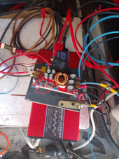
I am in the process of creating a charge system to lifepo4 battery in my van, so my setup will have:
1. DC-DC boost converter (3 units at 30A), this unit has a ConstantCurrent and low voltage protection, it is 1800W at 40A input booster from Aliexpress.
2. rectifier diode per booster unit to prevent back-feed
3. an arduino for temperature and voltage control to automatically switch on/off booster units.
4. relay to enable unit

and after watching this video I need to add temp sensor on the alternator :) just to prevent "magic smoke" from it.
My alternator is capable of 150A, so my idea was to draw max 90A, but now it need to be adjusted to the temperature levels.

below a picture of my test setup, that is just laid on the inverter inside the van, but it works and charges with 30A only when the engine is running, but when the ignition is on and engine off, the charge is about 5A (at the moment there is no planed external voltage control Arduino)

1721684053425.png


1721683712046.png
 

diy solar

diy solar
Back
Top