diy solar

diy solar

Analogic controller/diverter buck topology

120vjohn

New Member
Joined
Oct 3, 2021
Messages
40
Location
Romania
This circuit can serve both as MP-park two stages charge controller or as power diverter, if you want to use surplus energy to heat water or living spaces.
It is based on tl494/tl598 pwm controller, two voltage control loops are realized , one for input voltage, the converter starts above the preset voltage, to keep MPP point as charger use, or to keep the final charge voltage as diverter use, and an output voltage limiter loop, to provide final charge voltage as charger, or for safety redondance if is used with a diverter.
It can built in wide variety of voltage range from 10v to 1000v, reference schematics are for 100-300v range.
 

Attachments

  • vernoua.pdf
    94.7 KB · Views: 20
eeeeeeeee-diode, a little high tech for this place. I like the 494. To bad there isn't an updated version with a higher under voltage lock out for FET circuits. That can be a real killer in self powered circuits with slow voltage rise like solar panels in morning. Adding a pot to DTC can be useful to limit upper range in linear current booster mode. Many 120V AC wall wart type switching supplies can work above 60V DC at lower current. I use these 12V 1A versions from China that are $1.50 shipped. In slow voltage rise they can go into a half voltage stage so it is necessary to have a good UVLO.
 
This is originally designed for 100v (my batt string is LTO 55s 120v dc rated voltage) or above systems for home, controller is powered by an auxiliary SMPS that has it`s own UVLO, but I have one on a garden light that use a single 24 cells panel and ten 18650 li-ion cells in parallel and a single 3w led It works from tree years outdoors with no UVLO issues.
 
I mention this because your design is not complete for any single purpose and power supply sources may be iffy in some cases. Many FET driver chips do not have UVLO function. That isn't really a mainstream chip and substitutions could lead to real problems.
 
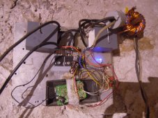
Here a picture with one as charger use 2xNTHL020N120SC1 as switch, for 3kw at 150v input,
 

Attachments

  • DSCN2905.JPG
    DSCN2905.JPG
    227.4 KB · Views: 3
This circuit can serve both as MP-park two stages charge controller or as power diverter, if you want to use surplus energy to heat water or living spaces.
It is based on tl494/tl598 pwm controller, two voltage control loops are realized , one for input voltage, the converter starts above the preset voltage, to keep MPP point as charger use, or to keep the final charge voltage as diverter use, and an output voltage limiter loop, to provide final charge voltage as charger, or for safety redondance if is used with a diverter.
It can built in wide variety of voltage range from 10v to 1000v, reference schematics are for 100-300v range.
Why are U1 and U3 "isolated" components when you have violated that isolation via R14 and R16?
U3 has a "floating" output with no reference to any ground?
Are you using a common ground across the isolation barrier?
 
Only the output of gate driver is insulated and it`s power, because the sorce of mosfet switches from gnd to vsw, the converter itself is not insulated, input port is +vsw, gnd, and output port is +vdc, gnd, ...gnd is shared by these two ports.
there is an error in this diagram driver pin4 is connected to mosfet source. reference of u3 is mosfet source
unfortunately i edited over it, i have this only as PDF
 
Back
Top