diy solar

diy solar

AOlithium -48v batteries to communicate with All-in-one (pylontech)

Derka181

New Member
Joined
May 11, 2023
Messages
69
Location
Canada
I have 4 - AOLITHIUM 51.2v 100ah Server Rack Lithium LiFePO4 Battery. In the manual its not clear on how to make all 4 communicate with “Pylontech”. All it says is jumper 32 (which is DIP 6-on) has to be set. It also is not clean if “slave 0” would be considered the first battery. Can someone help me on which jumpers have to be set to uses all 4 batteries. They informed me the the “CAN” port and the “RS485” port are invertchangable. I can use either port. IMG_5510.jpegIMG_5507.jpegIMG_5508.jpegIMG_5509.png
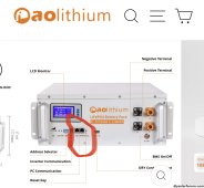
 
check the following

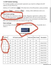
DIP 6 AKA address32 Tells the pc host or mainframe the master node;
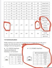
Your picture shows you the RS485 interface for all wires or pins labeled; CAN and R485 ports are simply labels on the Battery are interchangeable for most purposes in this pack except the master must use the CAN to the inverter BMS port (read 1.5 must use CAN interface)

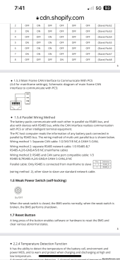
protocols use wires to communicate and baud rates; you must make sure the all line up to the master pack; for the rest of the packs use regular straight thru patch cables aka the RJ45 simple network cables named cascade cables in your package; The master cable is not a straight thru cable; pins 1,7 aka RS485b and RS485a respectively looking the picture you posted; master cable goes into CAN side of you master pack with DIP 1 thru 5 off and 6 up on (indicating master); I believe your picture showing the DIP all off for address 1 is for the PC monitoring where your master is the PC; as I understand it only have DIP 6 on for the master in closed loop


The rest are slave packs 1 thru 3 (assuming you bought 4) must have different addresses DIP1 on for slave pack 1 (binary or base 2 counting - aka 2 to the power zero in 1and so on according to the picture you posted - basically they must all have different addresses; The first slave cable connects the master pack RS485 port since CAN side is already used; use regular cascade cable aka CAT 5/6 network or the cascade cables daisy chained just like any other battery manufacture out there; If you are lost use a SOK as the master;

I think you may be plugging in the wrong end in CAN port or your RS485 pins on the INVERTER BMS port is not what you think it is; The pin 1,7 side of the master network cable must be in the master pack port- you have to make sure the inverter side port pins lines up with the correct pins for RS485A and B respectively.

Did you buy a wire or make it up yourself? Inverter side pin and protocol must line up to talk; check it with multimeter

they must talk the same protocol - ;

If they do check your baud rate

Summary:


The Master cable must have the 1,7 in the CAN side of the battery master pack; and Master is indicated by DIP 6 being on; There can only be one master pack; the rest should have DIP 6 off;

If you are using CAN protocol it is Pins 4,5 that must follow thru to your inverter CAN pins

I should not have to say; only change addresses on you packs when you packs are off.

Next look at the inverter pin out in the invert manual.

Make sure you have chosen the right protocol in the inverter menus
 
did a search for you;

aolithium.com for their BMS picture thank Oke#


manual is for the 100A and corresponds to the AOLithum picture you have above
 

Attachments

  • 寰源 16S DR48200JC-02-01 BMS产品规格书,200A,200AH 2021-10-29 A1.pdf
    900.7 KB · Views: 57
  • 寰源 16S DR48200JC-02-01 BMS产品规格书,200A,200AH 2021-10-29 A1 en-US.pdf
    1.3 MB · Views: 50
battery setting for the above using CAN
Victron from Oke#

see BMS software and work from there
 
To follow up for @Derka181

The seemed to update the user guide considerable since your images were posted above. For some reason the new manual seems to ignore that there is a RJ11 port at all... there is some confusion on there end or they changed BMS configurations...

You will need to use the settings that they have illustrated for the MPP Solar / Victron inverters that use Pylon 485 communication and make sure the RJ45 cable has the correct pinouts for the RS485 ports. On the master pack try flipping DIPS 5 and 6 to ON and double check your network cable is wired correctly... an off the shelf network cable wont work.
 
@Derka81 have you discussed this with aolithium support? have you received confirmation that the BMS supports Pylontech over RS485?
The new manual leads me to believe it's only over CAN bus. However I'm also not clear on how much the BMS comms differ between the BMS with RJ11 and the one with all RJ45 connections and firmware 2.x.
I eventually got a reply from support, seems they had to do a round of questioning with the BMS supplier/engineers...

Sounds like this BMS only supports CAN communications in the way we are used to (master-slave) and the 5th and 6th DIP switches are likely only switching of CAN protocols.

They did say that Voltronic can be connected over RS485 but it can only talk to 1 pack (no master-slave) but they did not say how this is accomplished (which port and which address configuration).

So its basically not worth it connecting a stack to the Voltronic units with 485 communications.. (Sungold SP6548, MPP LV6548, EG4 6500EX, MLPS 6500EX, etc...) Very misleading statements on the sales page.

Another good reason to check out the 6000XP, this pack is known to work with it.
 
Back
Top