diy solar

diy solar

Calculating Wire Length/Size with Van Chassis Ground

Tony

New Member
Joined
Nov 22, 2019
Messages
81
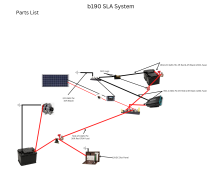
Hi, I'm relocating a house battery to inside the living area of the van in anticipation of upgrading to LiFePO4 battery w/dc-dc charger later. Primary charging will be from the alternator with small solar as secondary. Wire size calculators are looking for the round trip (RT) distance. The starter battery and alternator (in the engine compartment) negatives are wired to the chassis ground. My plan is to run a positive cable to the solenoid/battery separator and tie the house battery to chassis ground near the house battery. So, how do I calculate the RT cable length from the house battery to the solenoid/alternator in this situation?

Tony
 

Attachments

  • b190 SLA System.png
    b190 SLA System.png
    308.5 KB · Views: 18
The circuit is asymmetric so round trip distance is not meaningful.
The round trip distance is used to determine the circuit resistance and assumes the negative and positive conductor are the same resistance.

Its probably ok to just double the length of the positive conductor to determine how thick the positive conductor should be.
If you use the chassis as a high current return path you should upgrade the "big three".
The "big three" wires are; engine to frame, frame to battery negative and alternator to battery positive.
 
To be on the safe side I would suggest using total round trip not a one-way plus negative to chassis. Better to be one size to large that one size too small.

Are you using: https://www.explorist.life/wire-sizing-calculator/
AHTrimble, Thanks. I had done as you recommend (and thus the larger wire size.) Yep, I have the explorist site up! It called for 1/0, so I was planning 2/0 on the positive and negative sides of the path.
 
The circuit is asymmetric so round trip distance is not meaningful.
The round trip distance is used to determine the circuit resistance and assumes the negative and positive conductor are the same resistance.

Its probably ok to just double the length of the positive conductor to determine how thick the positive conductor should be.
If you use the chassis as a high current return path you should upgrade the "big three".
The "big three" wires are; engine to frame, frame to battery negative and alternator to battery positive.
John, Thanks. Yes, I expected chassis resistance was different. Battery/alternator cables are 4 awg. I wasn't planning to upgrade those. I'm expecting 50A max (25 amps standard) from the alternator.
 
T
AHTrimble, Thanks. I had done as you recommend (and thus the larger wire size.) Yep, I have the explorist site up! It called for 1/0, so I was planning 2/0 on the positive and negative sides of the path.
The old saying, "better safe than sorry" has been around a long time for good reason :)
Nate has some good info on his site doesn't he?
 
T

The old saying, "better safe than sorry" has been around a long time for good reason :)
Nate has some good info on his site doesn't he?
Yeah. Great resource. I found his site while searching for answers to my question.
 
How hard would adding a negative cable be?

I would not call a chassis ground standard for high wattage items on builds off this site, but it is done.
 
How hard would adding a negative cable be?

I would not call a chassis ground standard for high wattage items on builds off this site, but it is done.
Chrisski, it would mean just adding ~$120 negative cable cost? The house battery negative is currently chassis grounded. That circuit is just for charging the house battery. Other than extra voltage drop associated with the chassis ground, anything I need to worry about?
 
Other than extra voltage drop associated with the chassis ground, anything I need to worry about?
You might get less voltage drop.
Steel isn't very conductive but there is over a metric ton of it which helps.
 
I’m not a pro when it comes to grounding, but you will be one of the only ones on the forum using a frame ground for high wattage.

What stopped me from doing that is some of the grounding points I’ve cleaned over the years. Corrosion, grease, paints creating bad connections.

That stuff is fine for a normal house battery running lights and a fan, perhaps 10 or 15 amps tops, but once you throw in an inverter that has 200 amps to run a microwave, things change.

Same thing with a lot of the grounding connections are simply a star washer on paint tightened to go through the paint.

In my diesel truck which could have a 45 amp alternator, bad grounds appears as lower voltage.

It’s not that it can’t be done, but I’d be losing sleep over frame grounding on an inverter or battery in my RV on any build that would have high wattage.

I could be overly cautious, and I’m never the first on my block to do something.
 
I’m not a pro when it comes to grounding, but you will be one of the only ones on the forum using a frame ground for high wattage.
I'm ok with that.
What stopped me from doing that is some of the grounding points I’ve cleaned over the years. Corrosion, grease, paints creating bad connections.
Agreed, the connection points need to be selected and prepared carefully.
That stuff is fine for a normal house battery running lights and a fan, perhaps 10 or 15 amps tops, but once you throw in an inverter that has 200 amps to run a microwave, things change.
Agreed, the battery isolator won't protect the alternator from the potential draw of the house loads and/or a deeply discharged house battery.
Same thing with a lot of the grounding connections are simply a star washer on paint tightened to go through the paint.
Not good enough in my opinion.
I suggested that the OP upgrade the "big three".
I could be overly cautious, and I’m never the first on my block to do something.
I'm often the first to do things but I think before I act.
 
I'm ok with that.

Agreed, the connection points need to be selected and prepared carefully.

Agreed, the battery isolator won't protect the alternator from the potential draw of the house loads and/or a deeply discharged house battery.

Not good enough in my opinion.
I suggested that the OP upgrade the "big three".

I'm often the first to do things but I think before I act.
Chrisski & John, Thanks. Chrisski noted the inverter, but if you look at the drawing the inverter is served by the house battery which will be less than 4ft from the inverter. This connection will be charging from the alternator (190A) only. The only way to terminate to a chassis ground is to get down to bare frame, terminate the connection and then coat the connection to avoid rust and other contaminants. The solenoid will separate the batteries unless the ignition is on and the alternator will be running, which should protect the starter battery.
 
Chrisski noted the inverter, but if you look at the drawing the inverter is served by the house battery which will be less than 4ft from the inverter. This connection will be charging from the alternator (190A) only.
When the isolator is closed the alternator will service part of the house loads.
 
When the isolator is closed the alternator will service part of the house loads.
Thanks John. You're right of course. I just thought the resistance difference of the two sources would have the house battery supplying the inverter. I'll have to look at the cabling closer!
 
Back
Top