diy solar

diy solar

Charge and discharge differential rates between packs

vsman

New Member
Joined
Oct 6, 2021
Messages
77
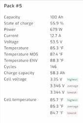
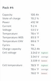
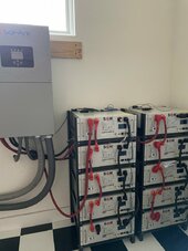
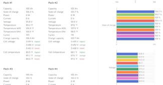
Noticed this recently. A few of my batteries are differentially discharging or charging faster than other packs.
In fact when it get really low I notice a strange behavior in that the system alternates between charging and discharging every 20-30 seconds. (I have a TOU setting when it drops below 20% it will grid charge)
 

Attachments

  • IMG_0628.jpeg
    IMG_0628.jpeg
    73 KB · Views: 16
  • IMG_0627.jpeg
    IMG_0627.jpeg
    65.5 KB · Views: 16
Batteries and all wiring must be PERFECTLY matched at every single level (cables, BMS, battery interconnects, inverter connection points, crimps, lugs, etc.) for perfect sharing of current.

When you get into the upper and lower legs of the voltage curve, things can get a little wonky.

Commenting on the images provided, 12% SoC variation with a 3.5A difference between battery currents is a non-concern IMHO.

Also of note is while I said 12% based on the Ah remaining, the difference is actually closer to 14% - another indication that battery SoC values are estimates.

Are you regularly charging your batteries to full/near full where all cells reach at least 3.45V?
 
I have a 100Ah and a 300Ah with totally imbalanced wiring. If I run a steady discharge or charge, I can see that they heave and ho a bit. One or the other will be slightly hungrier than it's proportional share at different parts of the voltage curve.

But it is ok, they will always catch up towards the bottom or top, they have to as the voltage curve steepens they simply cannot get any voltage spread from each other near the legs.

I would suspect that this is an internal series balancing problem in one or multiple of them. Mine never get more than 10 apart despite being different capacity on lopsided wired.
 
At 15% delta on a fairly low draw seems a bit high. Start by checking the connections are clean, tight and balanced. Especially on the 9.2a slacker.

Next would be to measure voltage drop at each of the connections to find the issue.
 
Batteries and all wiring must be PERFECTLY matched at every single level (cables, BMS, battery interconnects, inverter connection points, crimps, lugs, etc.) for perfect sharing of current.

When you get into the upper and lower legs of the voltage curve, things can get a little wonky.

Commenting on the images provided, 12% SoC variation with a 3.5A difference between battery currents is a non-concern IMHO.

Also of note is while I said 12% based on the Ah remaining, the difference is actually closer to 14% - another indication that battery SoC values are estimates.

Are you regularly charging your batteries to full/near full where all cells reach at least 3.45V?
1- I make sure atleast once a week it gets to 100% and sits there for a few hours. Can’t say I have noticed if the cells reach the 3.45V level- will check and circle back

2- haven’t had any change in setup since install over a year ago. But I’ll double check connections this weekend.

3- see attached picture for cables.
 

Attachments

  • IMG_0532.jpeg
    IMG_0532.jpeg
    114.4 KB · Views: 14
I make sure atleast once a week it gets to 100% and sits there for a few hours. Can’t say I have noticed if the cells reach the 3.45V level- will check and circle back
What's your bulk/absorb and float voltage? Or if you're not sure because it's controlled by the battery comms, charge them all the way up and see what voltage they're floating at after an hour at 100% float.

If your inverter is entering a repetitive charge/discharge cycle around the 20% mark and staying in that cycle, SOC errors are going to be accumulating (not worse than, but same as, any system actively meandering in the middle of the charge range).

Best assurance is to get communications with the batteries and observe them during the 100% charge state, looking for a delta of less than .020 between highest and lowest cell in each pack.
 
its been sitting at 100% now for an hour.Biggest delta is about 0.03V.
settings
Battery float charge voltage
57.6 V
Battery absorption charge voltage
57.6 V
Battery equalization charge voltage
57.6 V
 

Attachments

  • Screenshot 2024-06-07 211341.png
    Screenshot 2024-06-07 211341.png
    163.9 KB · Views: 7
I'm seeing 10 parallel batteries.
I'm seeing 7 at 57.5V
I'm seeing 3 at about 56.0V, and those three are reporting > 105% SoC.

Normally, I would conclude that you have three batteries in charge protection mode, but the cell voltages of batteries 1 and 2 don't suggest that.

Very odd.
 
You’ve zero current flow and way too much deviation in reported voltage. BMS calibration is off and that won’t make it accurate counting calories.
 
its been sitting at 100% now for an hour.Biggest delta is about 0.03V.
settings
Battery float charge voltage
57.6 V
Battery absorption charge voltage
57.6 V
Battery equalization charge voltage
57.6 V

I take it that this float voltage is temporary, just to hold packs at the top for some balance time?
 
What is the cell difference for each pack? Mine are .005v, but 0.030v could be normal for yours.

I would:
1) charge to 100% like you are currently doing.
2) immediately afterwards (while all packs are still fully charged) take pack 1, and hook it up as the only battery to the sol-ark, and charge it to 100%.
3) repeat with packs 2 and 4.
 
Have you used the SOKTools software to view each battery? The SOKTools software can be downloaded from the Current Connected Website https://www.currentconnected.com/sk48v100-owner-operators-manual/
Use the last link under downloads.

If you are using Solar Assistant simply move the RS323 to USB converter from Solar Assistant to your PC.
Before clicking "Open" in the "Serial Port" box, select FF for the Pack, this will allow you to monitor all batteries by selecting the battery number near the top of the screen.

For the batteries that do not seem to fully charge make a note of the "Charging" MOSFET indicator and the individual cell voltages. It's possible you have one cell that charges past Cell OV Protection which will stop the charge for the battery. Generally if a BMS reports an Alarm or Protection status the Master BMS reports this to the inverter which will display an alert/error code. Your inverter manual may list several "BMS" related error/fault codes

In addition if you are operating in "Closed Loop" the Master battery will report SOC for the entire stack as one battery. The inverter may stop charging once 100% SOC is reported. Does the inverter show 100% SOC even though several batteries are at a lower voltage? If you can get the lower voltage batteries to charge to a point where "Bal" appears next to the cell voltages the BMS will reset it's 100% SOC reference

You could consider disconnecting the BMS input to the invert (Open Loop) and opening the breakers on all batteries except the one you want to charge. You can manage/tweak the charge by changing the appropriate settings in the inverter. Some of these settings get overridden when BMS communications is enabled and the BMS cable is connected. Just keep in mind that if you take batteries offline you will have significantly less available battery power should the inverter need it if output load is increased (and PV power drops).
 
What I’m seeing is a total difference 1.3 volts between the highest and lowest packs at full, finished, absorbed charge. At this point even with only mediocre cable quality they should be the same (max .1 difference due to rounding out the number). This is most likely an issue with a bms reporting error. These are on three packs and they are also coincidentally showing over 100%.

I see that the packs are networked. Have you observed the packs going into float mode after absorption(around 55.2 volts) ?


IMG_1486.jpeg
 
These are DIY batteries, all 230 Ah EVE cells. Battery A always delivers a little more current on discharge and pulls a little more on charge. The 16 cells in battery A were purchased in 2021 through the Michael Caro debacle. Battery B cells were purchased from Docan in 2022. Battery C & D cells came from Docan in 2023. All 4 BMS are identical Overkill and all 4 are connected with meticulously measured and crimped identical cables & breakers to a common bus. The cell voltages and current settings in each BMS have all been calibrated at the software level. Although it plays havoc with my OCD, the system actually works well. The SOC and current measurements when added together match what’s being reported by the Victron shunt. Things start out evenly, battery A will diverge throughout the discharge curve, and everything evens out again below 20%. Although I’d like to know why, it is what it is and I quit worrying about it. 46F0F359-0012-46E4-B9C1-A7D5C81E66EB.png
 
Last edited:
@vsman , The other thing you might consider is using positive and negative bus bars where each stack of batteries connects to the bus bars and the inverter connects to the bus bars via an appropriate T-CLASS fuse
 
These are DIY batteries, all 230 Ah EVE cells. Battery A always delivers a little more current on discharge and pulls a little more on charge. The 16 cells in battery A were purchased in 2021 through the Michael Caro debacle. Battery B cells were purchased from Docan in 2022. Battery C & D cells came from Docan in 2023. All 4 BMS are identical Overkill and all 4 are connected with meticulously measured and crimped identical cables & breakers to a common bus. The cell voltages and current settings in each BMS have all been calibrated at the software level. Although it plays havoc with my OCD, the system actually works well. The SOC and current measurements when added together match what’s being reported by the Victron shunt. Things start out evenly, battery A will diverge throughout the discharge curve, and everything evens out again below 20%. Although I’d like to know why, it is what it is and I quit worrying about it. View attachment 220638
I’ve managed throttle back my OCD a bit. I’m not too concerned about state of charge matching between packs so much except when full and absorption is done, then they are all 100% at least for a moment. Because my packs have different brands cells and different build dates, they all have, for a lack of a better phrase, different personalities. The Eve cells contribute or take more at a higher state of charge. The CATL cells are a bit more mid range and broad. It’s like watching a horse race with the bands going back and forth passing each other for position. Throw a heavy load on them for a long period and the patterns change again. Suddenly remove the load and then you see a bit of stealing from the other for a bit. So now I’m not overly concerned, just as long as the voltages are close at any state of charge and load. My shunt also shows the same state of charge (+-5%@half) as the pack average even if they haven’t been to full capacity for a week. A lot might depend on how good your bms can measure and cable resistance. Picture of a higher current and much later a sudden decrease with a bit of stealing going on. IMG_1487.jpeg


STEALING/ TRANSFERRING / BALANCING

IMG_1483.jpeg
 
Things are starting to align as we approach 60% SOC. Battery A is now delivering less current than the others.


IMG_7746.png
 
What I’m seeing is a total difference 1.3 volts between the highest and lowest packs at full, finished, absorbed charge. At this point even with only mediocre cable quality they should be the same (max .1 difference due to rounding out the number). This is most likely an issue with a bms reporting error. These are on three packs and they are also coincidentally showing over 100%.
This. Unless there are hundreds of amps flowing that 1.3V delta looks like a calibration error.
 

diy solar

diy solar
Back
Top