diy solar

diy solar

Contactor polarity orientation

hwy17

Anti-Solar Enthusiast
Joined
Nov 11, 2022
Messages
2,775
Location
Santa Cruz, California
I'm considering using polar contactors and separate charge and discharge circuits.

A polar contactor comes with a + and - terminal.

Is there a standard for the directionality of these markings? Is it that in a battery to load configuration, on the negative side, you would face the negative marked terminal of the contactor towards the negative terminal of the battery?

And then on a charging circuit, on the negative side, you would would face the negative terminal towards the charger?

Is there any reason you should actually place the contactor on the positive side for either a charging or a load circuit? I'm just used to seeing FET BMS on the negative so I assume I will contactor the negative on both circuits.
 
From Midnite:

"The MNEPV din rail breakers do have a polarity. The + on the bottom side of the breaker means it wants to be hooked up to the highest potential. That will be the PV+ in a combiner or to the battery + when connected to the output of the controller. Now you may think that the output of the controller is at a higher potential than the battery plus terminal. Wrong! When a controller fails it shorts battery + to battery -. The battery+ terminal is the real highest potential when the controller fails. That condition is when you need the breaker to trip. I have found that unless you are at the top end of the voltage rating and at very high current, these din rail breakers trip just fine even hooked up backwards. Do it right though. It doesn't cost any more."


Single pole:

Between MPPT and PV, breaker (+) to (+) of the array, breaker (-) to (+) input of MPPT

Between MPPT and battery, breaker (+) to battery (+), breaker (-) to MPPT (+)
 
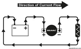
1699102719208.jpeg
So this diagram from Gigavac confirms my initial understanding of polarity on a load circuit. Positive faces battery positive and negative faces battery negative.

The reverse would apply on a charge circuit when breaking a charge. I.e. BMS says "stop! stop charging me!" and releases the contactor from the working charger you would want contactor positive facing charger positive or contactor negative facing charger negative.

Midnite's advice about breakers paints a different picture where in a charge controller failure the circuit shorts and turns into a load circuit, and then if you were using the contactor to break the short circuit load you would want it in a battery to load orientation.

I think I have to conclude that Midnite's advice applies specifically to breakers that are providing overcurrent protection. Whereas on my circuits where a T-Class fuse will serve the ultimate OCP and the contactor is for charge interruption I should in fact use the reverse orientation, treating the battery as the load.
 
Oh I think I've just realized a problem. You cannot parallel separate BMS/batteries on separate charge and discharge circuits.

If one battery went into charge disable, it would remain connected to the charge source by another battery that is in charge and discharge enable.
 
Or you could, but the charge and discharge circuits would each need a master contactor, controlled by series relays, and then any battery going into charge disable would open the entire charge circuit to all batteries.
 
A possible advantage of a master contactor system would be that if one battery goes into charge disable, the whole bank switches to discharge only, keeping it in voltage/SOC sync rather than the problem battery sitting out the rest of a charge cycle.

But then if you have one battery way out of balance and its usable capacity is 50% or something, the whole bank is limited to that capacity.
 
Last edited:
Back
Top