diy solar

diy solar

Design of AGM & LiFePO4 / Solar system for my boat

While we are concerning ourselves with wire and bus bar resistance and the potential voltage differences . . .

00 AWG copper has a resistance of approximately 0.079 ohms/1000 feet.​
My 33 inch battery lead wires (call it 3 feet) have a resistance of . . . 0.079/1000 x 3 = 0.000237 ohms​
@ 100 amps current (per battery) the expected voltage drop across the wires would be . . . 0.000237 ohms x 100 amps = 0.0237 volts.​
Figuring voltage drop across both the + and - leads . . . 2 x 0.0237 = 0.0474 volts​
Of the several boats that I've owned over the years, this boat has the largest size wiring of all of them. I think my other boats had only 2 AWG wiring by comparison.
 
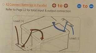
There is one additional consideration that the installation manual makes note of in larger battery arrays (4P, etc), is to join the batteries together for balancing. They don't show it in the simple 2 parallel installation, but it still could apply, because it is one of the preparation steps outlined in the manual.

  1. Fully charge each battery to the same resting voltage.
  2. Connect the batteries together in parallel and let rest for 12-24 hours.
I could add a wire between the batteries (updated picture below), but I'm assuming they will tend to balance any way by virtue of their common connection at the bus bar.

FWIW - the battery cables are 2/0 (00) AWG with crimped and soldered connections each are 33" in length. I believe they are/were sized by the boat manufacturer for 100+ amps, based on the typical runs to the main power-consuming components in the boat. (Inverter, Engines, windlass, etc)

The most power consuming component on the boat is the 2000 watt inverter, which (theoretically) could draw about 165 amps at full load. The most I've seen it draw on a single load is 40 amps (powering the air conditioner). I have a small microwave oven that needs about 1000 watts to run, but the inverter won't run it unless it has 120 VAC shore power connected. I assume the microwave would need upwards of 100 amps into the inverter to generate the 1000 watts @ 120 VAC that it needs.


If you are going to bridge(?) the batteries, this an the accepted method and it wont matter which end of the buss bar you connect to:
24vBatteryConnection4.JPG
And it's important to make sure the lengh between the positives and the length between the negatives is the same as closely as possible. If you are connecting them directly to the buss bar, the negatives all need to be the same length to their buss and the positives the same length to their buss as shown in the original diagram in the book.

Let me see if this makes sense: If you lay out the batteries in a north south pattern (2 or more batteries) and the Neg is on the west and the Pos is on the east, then you want all the Neg cables to the buss bar the same length and all the Pos cables to their buss bar the same length. NOW HERE IS THE THING THAT GETS MISSED: If you connect the System Neg to the North end of the Neg Buss, you want to connect the System Pos the the SOUTH end of the Pos Buss. If you connect both the north end, the battery that is on the north end will degrade fastest. Electricity wants to follow the path of least resistant which is usually the shortest distance. The batteries farthest from the load will get the least "use" in the circut.

If you watch Will's videos where he installs multiple rack batteries, he specifies that if you connect the Neg to the bottom of its buss, you connect the Pos the TOP of its buss (or viceverse) . I've been changing out battery packs in large server rack UPS' for 20+ years and had completely missed that they were wired like that (thankfully I was only swapping the batteries and not rewiring anything).

Hope this helps.
 
I'll keep the wring options under consideration, but I'm onto the DC-DC charger configuration and my alternator woes.

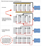
Here are the 4 prescribed ways of configuring batteries in parallel as shown on the Victron website.

Screenshot 2024-04-24 at 10.46.20 AM.png

I have essentially used the a combination of the first and second method, which corresponds to the installation manual.
 
Last edited:
Back
Top