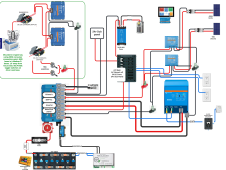
This is a 3rd stage preliminary drawing overview. Ive posted previously regarding portions of this, but now realize a bigger picture would facilitate moving forward. I am an accomplished DIY'er yet this is my first electrical challenge. To get to this point has taken me a tremendous amount of time schooling up... including learning a flowchart program (Lucidchart) FAR more than anticipated. BUT, despite wanting to get it done i truly want to get it right.
Pleas keep in mind ive left out cable sizes, fuse sizes etc for now.
Having read many similar postings, i see that what often happens is the first person to reply sets a "tone" and others often don't want to offer contrary or conflicting advice. The thread gets hijacked or eventually buried. I really do need some help with this, so if you're reluctant to do so publicly please feel free to PM me. Also, i am willing to pay an experienced person for some "consultation", so please PM me if you can. Honestly the more input i can get the better.
Some "firm non changeable's" 24V, battery is already built, Orions mounted in engine bay, 12V system already installed. Ive already purchased most of the components in the drawing.
I planned to use the Electrodacus SBMS0 originally (and may yet if its ever available) but for now its the 100a Overkill BMS. It may prove adequate for my eventual 120V loads but its kinda marginal...
Here's the drawing with some specific questions/concerns following

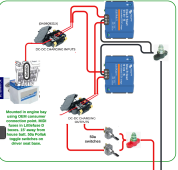
I was surprised by how involved the Orion's were, especially the numerous fuses. Did i over complicate this area?

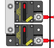
What about these lug/post/connectors, especially for the MPPT's/Orions? or should i use?
bused together?
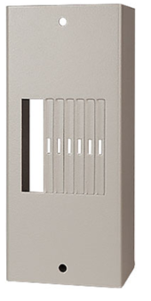
Can i use this MidniteSolar (or sim) for the main panel instead of the BluSeas?
Please offer up ANY suggestions, thoughts, ideas. This forum has been great help. Thank you!
Pleas keep in mind ive left out cable sizes, fuse sizes etc for now.
Having read many similar postings, i see that what often happens is the first person to reply sets a "tone" and others often don't want to offer contrary or conflicting advice. The thread gets hijacked or eventually buried. I really do need some help with this, so if you're reluctant to do so publicly please feel free to PM me. Also, i am willing to pay an experienced person for some "consultation", so please PM me if you can. Honestly the more input i can get the better.
Some "firm non changeable's" 24V, battery is already built, Orions mounted in engine bay, 12V system already installed. Ive already purchased most of the components in the drawing.
I planned to use the Electrodacus SBMS0 originally (and may yet if its ever available) but for now its the 100a Overkill BMS. It may prove adequate for my eventual 120V loads but its kinda marginal...
Here's the drawing with some specific questions/concerns following

I was surprised by how involved the Orion's were, especially the numerous fuses. Did i over complicate this area?

What about these lug/post/connectors, especially for the MPPT's/Orions?
 or should i use?
bused together?
Can i use this MidniteSolar (or sim) for the main panel instead of the BluSeas?

Please offer up ANY suggestions, thoughts, ideas. This forum has been great help. Thank you!
Last edited:


