demongman7
New Member
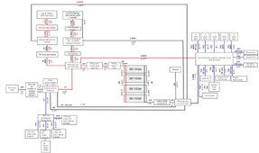
Hi - if anyone would be kind enough to take a look at my wiring diagram, I would greatly appreciate a second set of eyes. I included a few details on how I processed the sizes below, along with specific questions I'd like to double check. Know it's a big ask, so no pressure if this type of request isn't appropriate.
Process: Generally I used the Blue Sea Circuit calculator, plugged in the max current for the component / device, and my distance; then chose a fuse that was lower than the capacity provided on the calculator per ABYC standards. This will be done inside a 2018 Ford Transit 350 HD.
Sketchup file for electrical box

Questions:
1. I'm a bit confused on the 'round trip' length that should be considered for derating. For example, from my alternator to the first breaker, there is no round circuit, it's just 1.25 FT. Should this length be used, or should I base the wire on the full circuit of alternator > breaker > DC-DC charger > negative bus bar, etc.?
2. For the multiplus output, I thought I'd read in the manual that max charge was 75A, (and my distribution panel is 50A), is there a reason why I'd have to use 6/3? Have seen some comments on the forum here suggesting 6/3 is required per Victron recommendation.
3. Is it critical to get all Blue Sea branded components? Are there other reputable brands that are more cost efficient?
4. I'm really uncertain about the wire size in between alternator and DC-DC charger; I've seen in another thread here that realistically it's near impossible for alternator output to be even close to 225A, but I want to be conservative so is 1AWG okay then switch to 6 after the breaker? Further I've seen 3 different recommendations per Sterling for breaker size. In fact, the recommended breaker differs in the English manual vs. German. Should I go 70A or 100A on both sides?
5. I've included a SketchUp file here of my electrical components' locations (the box will be closed in but I've hidden the walls to view easier) - are the fuses all close enough to the battery? Targeted sufficient spacing for multiplus per manual, but recognize it's tight. Also have propane locker nearby (double walled). Is my battery stacking nuts? Saw another forum member do something similar and BB manual says any orientation is ok.
6. Anywhere I can safely slim down or suggestions/ideas to cut costs? Budget has quickly become tight lol. Thought about doing fuses instead of breakers, but the fuse holders (ANL/mega) combined with the actual fuse cost seem to come close to blue sea breakers.
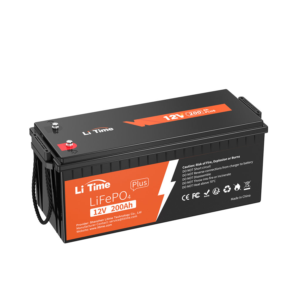
7. I know the charge controller is overpowered - I called BattleBorn and they said this won't be an issue, but appreciate any other perspectives if it will be critically risky (already have purchased and can't return unfortunately).
8. Should I connect my Charge Controller to the multiplus?
9. Is there any particular way the negative & ground from the multiplus should be wired to the negative bus bar? Can I just wire them to the same terminal?
10. Victron manual for charge controller specifies 2AWG for PV/battery terminals - can I go lower than this? Seems like 8AWG should be plenty for my purposes.
11. Is 600A overkill for my main switch? Seems like next model down is only 350A. Is AFD needed?
Process: Generally I used the Blue Sea Circuit calculator, plugged in the max current for the component / device, and my distance; then chose a fuse that was lower than the capacity provided on the calculator per ABYC standards. This will be done inside a 2018 Ford Transit 350 HD.
Sketchup file for electrical box

Questions:
1. I'm a bit confused on the 'round trip' length that should be considered for derating. For example, from my alternator to the first breaker, there is no round circuit, it's just 1.25 FT. Should this length be used, or should I base the wire on the full circuit of alternator > breaker > DC-DC charger > negative bus bar, etc.?
2. For the multiplus output, I thought I'd read in the manual that max charge was 75A, (and my distribution panel is 50A), is there a reason why I'd have to use 6/3? Have seen some comments on the forum here suggesting 6/3 is required per Victron recommendation.
3. Is it critical to get all Blue Sea branded components? Are there other reputable brands that are more cost efficient?
4. I'm really uncertain about the wire size in between alternator and DC-DC charger; I've seen in another thread here that realistically it's near impossible for alternator output to be even close to 225A, but I want to be conservative so is 1AWG okay then switch to 6 after the breaker? Further I've seen 3 different recommendations per Sterling for breaker size. In fact, the recommended breaker differs in the English manual vs. German. Should I go 70A or 100A on both sides?
5. I've included a SketchUp file here of my electrical components' locations (the box will be closed in but I've hidden the walls to view easier) - are the fuses all close enough to the battery? Targeted sufficient spacing for multiplus per manual, but recognize it's tight. Also have propane locker nearby (double walled). Is my battery stacking nuts? Saw another forum member do something similar and BB manual says any orientation is ok.
6. Anywhere I can safely slim down or suggestions/ideas to cut costs? Budget has quickly become tight lol. Thought about doing fuses instead of breakers, but the fuse holders (ANL/mega) combined with the actual fuse cost seem to come close to blue sea breakers.
7. I know the charge controller is overpowered - I called BattleBorn and they said this won't be an issue, but appreciate any other perspectives if it will be critically risky (already have purchased and can't return unfortunately).
8. Should I connect my Charge Controller to the multiplus?
9. Is there any particular way the negative & ground from the multiplus should be wired to the negative bus bar? Can I just wire them to the same terminal?
10. Victron manual for charge controller specifies 2AWG for PV/battery terminals - can I go lower than this? Seems like 8AWG should be plenty for my purposes.
11. Is 600A overkill for my main switch? Seems like next model down is only 350A. Is AFD needed?


