chris_the boat dude
New Member
- Joined
- Jan 16, 2022
- Messages
- 5
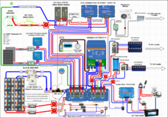
Hello, looking for peer review and critique for my proposed wiring schematic on my 45ft glass fiber sailboat. This is edition 1 so I expect there to be some faults.
This was drawn using draw.io with the addition of a Victron products html file and many copy pasted images off the web. Very simple but very time consuming. There is a great video on you tube about the basic operation of draw.io (search REC BMS diagram net demo)
Following are some initial questions I have:
Chris
This was drawn using draw.io with the addition of a Victron products html file and many copy pasted images off the web. Very simple but very time consuming. There is a great video on you tube about the basic operation of draw.io (search REC BMS diagram net demo)
Following are some initial questions I have:
- Starter circuit – grounded to engine – no other return to starter or alternator. How it was (is) setup by marine electrician. Normal? Problematic?
- is the engine block my ground for all systems (starter/12v/24v/220v) ... should I be setting up a grounding plate/bus? As opposed to running the 2x50mm cables direct to engine block.
- Grounding in general – this topic seems widely accepted as extremely confusing… I agree… what corrections need to made to my proposed grounding.
- 2x Orion tr smarts isolated for starter -> house charging - the units I have are the isolated versions. The starter batteries are grounded to the engine block. I assume they will still function perfectly well, im just curious about what this does the ísolation of the units
- 2x Orion tr smarts isolated for starter -> house charging - 30 amp mrbf fuses at the battery post as per recommended in manual… minimum fuse available for lynx distributor is 40 amps…problem?
- I understand that the dual 17A Orion TR´s will draw 75% of the capacity of the 45amp alternator. In the future I hope to upgrade the current alternator. For the mean time I will monitor closely the temperature with a flir camera and act accordingly. (wondering if it is possible to derate the orions on the app?)
- No cerbo gx at this stage. May use a raspberry pie in the future with Venus software. For now im happy monitoring via apps/mk3 adapter.
Chris