diy solar

diy solar

Please review my panel setup

CaliSunHarvester

Solar Enthusiast
Joined
Dec 25, 2022
Messages
471
Location
Santa Cruz, California, USA
In the past, I built an off-grid 24V system with a 3kW inverter and 3kW panels, which I use to power a detached workshop, and to charge a PHEV. This has worked well for a little over a year. So I felt confident, to build a somewhat larger system with 25kW storage on 48V basis. This one should power a portion of my house. I put the inverter/ charger (SGP 10kW model) in a separate shed and ran the output into the room where the PoCo's main panel is.

I added a new blank panel left of it.
Image1.jpg
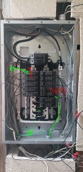
This first diagram shows the existing panel. The right panel is the old one, gets power from the utility and has a bunch of breakers and tons of wires in it. The left one is blank and clean.

My expectation was to identify wires that belong together e.g. for circuit 2 -- 1 hot (black), 1 neutral and 1 ground wire.
I would then swing these 3 over to the new panel.
PV system 2.jpg

Unfortunately, I very quickly realized that there were 40 circuits with 40 black (or red) wires, but only 5 bare copper ground wires. It seemed impossible to match them. Also, I had found places in the house with other grounds, e.g. inside a wall of a bathroom, a white wire was hooked up to a metal pipe.

So, instead, I could only move over a pair of black and white:
PV system 3.jpg


-- PAUSE --

This alone got me uncomfortable already. Knowing that my new "off grid circuit 2" was grounded -- who knows where. Keep in mind, there are some pretty big neutrals and big grounds coming into the main panel. They could belong to the 30A, 60A and 100A breakers. But it's also possible that the ground for circuit 2 is attached to one of those.

However, it has been working so far. Today, I was about to move my 8th circuit over, from the right to the left. The original panel has space for 40 breakers, meaning 40 black wires, but not 40 white wires either. Remember how I said "only 5 bare copper ground wires"? I should have added "at most 20 white neutrals".
And since I already swung over 7 white ones, there were like 10 left for me.

And none of them seemed to belong to the 8th circuit. I identify the matching neutral by creating an artificial "short" in the circuit (both panels powered off, of course), and then I look which of the white wires shows continuity with the black wire that I plan to move over.

I removed all white wires in the right panel from the bus bar, and the black one still had continuity with the bus bar on the right.

Worse, I noticed continuity with the left panel's bus bar.

My explanation is that some circuits in the old panel have their neutrals joined before they come into the panel, e.g. circuit 7 and circuit 8 are on one neutral. This matches up with the facts that 80% of the breakers are 15A only but the wire looks like 12 gauge and even 10 gauge.
When I moved #7 to the new panel, I already moved the neutral for #8.

So, today, I just hooked up the hot wire of #8 to a new breaker and hooked it up in the new panel.. things work

But now I'm really scared because of the continuity of the neutral bars in the 2 panels.

What do I need to do?


I should also add that the old electrical panel has a grid-tied solar panel installation. 40 solar panels with 2 inverters that are feeding into a double pole 30A breaker in the old panel. I am in California. So there is a rapid disconnect .. somewhere (not sure).
 
Last edited:
I suggest posting photos in case others notice things you aren't seeing. Esp since things are kind of bonkers here. Also I would recommend posting similar info to a general DIY electrical work forum, since you need a lot of help on this. Maybe diychatroom.com

What kind of cable is coming into the box/snaking away from the panels? I find it hard to believe that modern Romex with ground would lead to such a shitshow.

How old is the property / remodels? (this will maybe give some hints as to the code at the time of installation).

You might want to invest in a circuit tracer. Maybe even something moderate price, given the rats nest here.

Did you check how many MWBC you have? That would explain the Red/Black proliferation. With MWBC you would have 1/2 the number of neutrals. It would not explain the missing EGCs though. Each MWBC also need to be moved in pairs to opposite legs and handle-tied breakers.

Another approach is to "declare bankruptcy" and buy an inverter with 200A bypass, and hook that in front of what you have today. So any shitshow doesn't get worse from you trying to move circuits.

Keep in mind 250.130(C) - the EGC retrofit clause, allowing you to run EGC back if the circuit originally did not have it.

For circuits where the EGC is bonkers/non-existent, code has a provision to claw back some protection by replacing the safety of EGC with using a GFCI. That doesn't help that well the EGC is bootlegged into a place where it can be energized, but it does help if the EGC is insufficient and there is a ground fault that the EGC should have cleared.

If you want very strict checking of neutral usage, you can use GFCI or AFCI breakers where neutral lands on the breaker. These have a very high probability of flipping out if the current flow is imbalanced (IE, you didn't move the wiring correctly). You can buy a handful as a tracing aid, you don't need to replace all of them.

I should also add that the old electrical panel has a grid-tied solar panel installation. 40 solar panels with 2 inverters that are feeding into a double pole 30A breaker in the old panel. I am in California. So there is a rapid disconnect .. somewhere (not sure).
How old is this grid-tie install? You should be able to get info from POCO or get permits data from your AHJ. That will help inform what kind of disconnect you have. Note my AHJ allows the AC breaker to serve as a disconnect for microinverter system (I'm not sure about string inverter).
 
Hello, thank you for the response. I will need to digest it. Photos will come.

The house is built 1965. Grid tied solar is from 2004. There is some modern romex, but also other type of wiring. Not knob and tube. The panel is Stab Lok with really narrow breakers = maximum number of wires in minimum space.

I think the disconnect is outside. There are 2 boxes. Definitely a manual solar disconnect next to the meter. But I thought there is also an automatic solar disconnect in case of a power outage. Not sure where that is.

Did you check how many MWBC you have

I am estimating 6 to 8. Yes, that's why there are red wires. However, one of the 2 pole breakers has a white wire attached, I guess they ran out of material.

2 pole:
There's a 100A for a sub panel, a 60A for a sub panel, 30A water heater, 30A dryer, 30A solar, 30A heater, 30A heater, 30A wall oven.

I am not at the property, so there could be 1 or 2 more.


I do have a "breaker finder" from Klein. I guess that's not a full circuit tracer.


EDIT:
I believe that all outlets in this house are grounded.
 
Last edited:
There is some modern romex, but also other type of wiring. Not knob and tube.
There was this cloth covered proto-Romex stuff between NM-A and knob and tube. Without ground. My rental property has that.

I think 1960s predates requirement for EGC for most things. The fix is choosing either GFCI or retrofit ground, depending on requirement for real ground / maybe what the risk is based on the equipment & location that is attached.

The likely shared neutrals is not good from a neutral overload angle (and it's probably code violation back when it was installed). I wonder if the circuit finder can help with that (IE induce a signal, then see which neutrals the signal comes in on). Dunno what's to be done about it, you can try to split, you can try to put 10A breakers on it (or even smaller) on circuits with suspected shared neutral to claw back some safety factor. No clue what the stab-lok is going to have.

You can also take the position to replace the problem one for one (well you can fix the ones you know how to fix) and splice everything out of that old panel.
I think the disconnect is outside. There are 2 boxes. Definitely a manual solar disconnect next to the meter. But I thought there is also an automatic solar disconnect in case of a power outage. Not sure where that is.
I don't know what was code in 2004 but this is done on modern inverters by stuff inside the inverter. I think it was there back then too, the POCOs pushed this into grid tie very very early. The keyword is "interactive power source" or "interactive inverter" if you want to do research. You can also check for yourself by cutting the breaker closest to the GTI and with confidence that there's nothing between the GTI and the breaker, you should see the AC on the lines coming into that breaker go dead within a few seconds.

However, one of the 2 pole breakers has a white wire attached, I guess they ran out of material.
This can also happen if /2 wire is used for a 240V circuit, both original install and if swapped up from 120V to 240V. Legal for cable (not for THHN) except they should have remarked the neutral on both ends / intervening boxes with splices
 
cloth covered proto-Romex

Yes, that's the one. I didn't realize it had no ground in it. Now it makes sense why there are some random grounds in various places, and only a few bare copper wires.


I don't know what was code in 2004 but this is done on modern inverters by stuff inside the inverter.

That makes sense. The original inverters from 2004 were heavy "Sunnyboys". They broke in 2016 and 2017, and I replaced them with SolarEdge ones, 3kW each. Both with the Sunnyboy and with the SolarEdge, when the power goes out e.g. tree fell on overhead wire.. very common here.. the property goes dark.

This was the motivation to take a portion of the circles "off grid".

Since I discovered continuity between the 2 service panels' neutral bars, I worry that in case of an outage, my off grid circuits' neutral energizes the public grid. Does this concern make sense?

(I haven't checked this continuity after moving circuit 8 over. But it's probably still there.)
 
Since I discovered continuity between the 2 service panels' neutral bars, I worry that in case of an outage, my off grid circuits' neutral energizes the public grid. Does this concern make sense?

(I haven't checked this continuity after moving circuit 8 over. But it's probably still there.)

Neutral connectivity is tricky, I think it might be required by code in some situations, and I think neutral switching is optional/not-recommended in the US anyway. Switching neutral brings in the risk of floating neutral killing 120V appliances and probably also floating the grounding system it's bonded to. (Now if the grounding system is still bonded connected to utility neutral it will get pulled back down, at the expense of having current now going over ground which may cause damage).

One way to test/get intuition -- if you have AC-In going into your SRNE 10K (and this is going to be 120/240 most likely if you hope to transfer back to grid) then an unswitched neutral within the SRNE10K means that regardless of the transfer state there will be continuity between the CLP that the SRNE10K is feeding, and the other panel's neutral. You can try disconnecting all neutrals from the CLP, but leave the SRNE10K connected & powered off. I would bet there is neutral to neutral continuity.

Alternatively you can fully disconnect SRNE10K and then test continuity when off between the AC-in neutral and AC-out neutral. And double check that by testing AC-in L to AC-out N's voltage difference.
 
if you have AC-In going into your SRNE 10K

Your posts are full of information and I need to look up several acronyms or phrases for each of them. Learning a lot. I appreciate your help very much.

But one thing I do know without google:

I do not have anything connected to AC-in on the SRNE. Because I want the off-grid portion to be 100% separated.


Switching neutral brings in the risk of floating neutral killing 120V appliances and probably also floating the grounding system it's bonded to.


This is just so over my head.

But let me share a scary moment.

A week ago, when I had just 4 circuits moved over into the new panel, I didn't like the location of a neutral wire. My idea was to have each neutral behind it's matching breaker. It is a GE panel with 2 neutral bars left and right. The neutral for the fridge was on the correct bus bar, but - for optical reasons- not in the perfect spot.

So, I did NOT turn off either panel. I flipped of the circuit for the fridge. Removed the neutral for the fridge. In this moment, I notice a flicker in the CFL ceiling light fixture in the room that I am in. Which is on the new panel, but a separate circuit. Then I hear screaming from the bedroom (also on solar, yet another circuit).

I quickly turn off both electric panels. Run next door.

Smoke was coming out from the "smart light switch" (one of those with WiFi for home automation). I learn that the ceiling lights suddenly came on.. very bright.

The switch had apparently received high voltage (240V?) and, even though "off", let it through to the LED cans. 4 of 6 burnt out.

I never had an arc when disconnecting the neutral in the panel.

Edit: I found out that the fridge works on anything AC 90V to 390V

I need more of that LOL
 
Last edited:
Yup that is what happens if you have devices “off” and breaker on and then you disconnect a neutral. You created a floating neutral situation and counterintuitive stuff happens to the stuff on the circuit.

One of the numerous ways you can screw yourself with MWBC (which BTW has a lot of random bits scattered around the code to protect against all these gotchas. Which is great except it’s hard to know all of those)
 
Here is a picture of the 2 panels at the start of my activity. I had installed a temporary 120V outlet on the new panel. There's a bit of romex coming in from underneath.
20231225_135128.jpg

This is the wiring coming from the ceiling. The exterior wall is brick and this section got furred out to allow for the wires to run to the panel.
20240125_140817.jpg

And this is the Stab-Lok panel as it looks right now. As I said, I moved 9 (not 8) circuits over. I marked the removed breakers purple, some I left the breaker in and just removed the wire.

At the bottom, in green markup, you see 6 wire nuts/ connectors. Those are the neutrals. Wait, it should be 8 per previous post. 2 more are outside the picture. Those 2 neutrals came from the top and were long enough to run into the new panel. So, 8 neutrals (green markup) are connected. 9 hots (purple markup) have been moved over.

As an extra bonus, hot pink marks the 2 wire nuts that the installer put there to stabilize the breakers. They are kind of lose in there.

20240125_143145.jpg
 
Last edited:
As you can see, there are 9 or 10 of the smaller neutrals at the bottom connected to the neutral bar.

And about 25 of hot wires (black, red and a few white) in size 12 or 14 gauge. Some could be 10, hard to tell.
 
my main concerns are:

1) safety of this setup during normal operation

2) will my off-grid panel energize the utility line during an outage?

For (2), I did this:
Turn off the main breaker for the right (utility panel) and keep the off-grid panel energized.
Measure in the right panel between L1 and N if there is voltage. And between L1 and L2 and between L2 and N.

I measured less than 1V between L1 and N, and between L2 and N.

I guess that's good news.
 
Last edited:
As you can see, there are 9 or 10 of the smaller neutrals at the bottom connected to the neutral bar.

And about 25 of hot wires (black, red and a few white) in size 12 or 14 gauge. Some could be 10, hard to tell.

Looks like a lot of the black/white are on breakers spanning both legs (this looks like GE panels where you can offset by one position to get both legs from a 1" breaker). And there's probably some confusion between how the half breaker and full breakers are supposed to be used, looks like maybe a lot of places where they just grabbed breakers that would work but not have common trip / handle ties. IE, if the white wires are part of 240V, they would be on opposite leg from black (ideally they should be on common trip breaker but I can see a lot that seem to be separate tandem breakers, at best with handle ties. Common trip = if one leg overloads both legs get disconnected, physically this is one solid piece of plastic. Handle tie = reminder to turn off both at the same time. Two pieces of plastic with some metal connecting them (on some brands you can have handles that look like they are only handle tied but are actually internally common trip).

Are there common grounds going through conduit? You have a couple large conduits in there, they can probably fit 4 circuits each (4 = limit of correct derate, they could have stuffed more in there), so that is a way to have fewer ground on the newer circuits.

my main concerns are:

1) safety of this setup during normal operation

2) will my off-grid panel energize the utility line during an outage?

For (2), I did this:
Turn off the main breaker for the right (utility panel) and keep the off-grid panel energized.
Measure in the right panel between L1 and N if there is voltage. And between L1 and L2 and between L2 and N.

I measured less than 1V between L1 and N, and between L2 and N.

I guess that's good news.

Hmm, maybe measure between L on utility panel and N on the off-grid panel (with the power off). I think this will check that there isn't weird stuff like hots from two circuits connected somewhere in the hosue.

I think it would be possible for your off-grid panel to energize the utility line if only the neutral/grounds are electrically connected to each other. This will happen through the EGC unless you drive different set of ground rods (I don't think this is allowed for the same building). The only way to push power back through the utility transformer is if you form a circuit with the secondary, so even if you somehow lift the neutral voltage relative to ground, it shouldn't push back onto the primary lines.

However, it has been working so far. Today, I was about to move my 8th circuit over, from the right to the left. The original panel has space for 40 breakers, meaning 40 black wires, but not 40 white wires either. Remember how I said "only 5 bare copper ground wires"? I should have added "at most 20 white neutrals".
And since I already swung over 7 white ones, there were like 10 left for me.
The limit on neutrals is related to the maximum number of circuits the panel is designed for. They probably expected folks that needed more than 20 120V circuits to make some of the additional with MWBC.
But it's also possible that the ground for circuit 2 is attached to one of those.
I believe this is allowed by code (retrofit ground connected to existing ground). Connecting to water pipe I don't believe is allowed. There should be only one ground in the building anyway, at the same voltage. They would differ in how big of a circuit they are rated for.

Since I discovered continuity between the 2 service panels' neutral bars, I worry that in case of an outage, my off grid circuits' neutral energizes the public grid. Does this concern make sense?
Continuity is expected through the ground if they are properly connected. If you remove all grounds from off grid panel and make sure off-grid panel has N-G bond removed, is there still continuity neutral to neutral?
 
black/white are on breakers spanning both legs

Well, I was not really worried about white wires connected to breakers. I have seen an electric water heater with 2 elements hooked up with 10/2 romex (somewhere else).

The following picture has numbers for breakers:
20240126_083444.jpg
I believe 6/7 is the solar feed. I don't know what 5 and 8 are, but there is a SOLAR label covering 5-8.
8, 10 are single pole with white. 10 per 1965 label is something in the kitchen.. not confirmed by me.

On the right, 26/27 are one common trip breaker. Probably a heater somewhere (unknown).

38 has a white wire in a single pole breaker. I don't know its purpose. Note that 39 is a 20A as well.. and I have not identified 39 either.


I did read more about MWBC and understand now that it's a trick to save a neutral wire. 2 separate circuits with a shared neutral.

Are there common grounds going through conduit?

It is really hard to see. I will try to find out.

The limit on neutrals is related to the maximum number of circuits the panel is designed for. They probably expected folks that needed more than 20 120V circuits to make some of the additional with MWBC.

So, I have the manufacturer's label here:
20240126_071519.jpg
20240126_071529.jpg
The section at the bottom has 40 places for neutral wires (38-40 are in the middle).

No space for ground wire back then?

On a side note, in the long run, I wish to replace this Stab-Lok panel with a new one from GE or square-D. Maybe when I have it down to 20 circuits.

Did you see the big silver SOLAR sticker across 5-8?

maybe measure between L on utility panel and N on the off-grid panel (with the power off).

Definitely will do this!!

If you remove all grounds from off grid panel and make sure off-grid panel has N-G bond removed, is there still continuity neutral to neutral?

The off-grid panel does not have an N-G bond. G goes back to the inverter. N and G are bonded at the inverter.
Now the embarrassing part.
Inverter is not grounded yet. I didn't know where to ground it. To the same ground as the house (I have multiple places to choose from LOL, probably the copper rod near the service entrance is best)?
Or should the inverter get its own ground rod? To have full separation, I mean.

If the 2 panels were on the same ground, I had not been surprised by N to N connectivity.
 
No space for ground wire back then?
If the panel is intended for use as main panel (either only works as main panel or convertible) then users are allowed to put grounds into the neutral bar. And if the panel did not ship with ground bar installed it's easiest to just use what's there.

On a side note, in the long run, I wish to replace this Stab-Lok panel with a new one from GE or square-D. Maybe when I have it down to 20 circuits.

Did you see the big silver SOLAR sticker across 5-8?

Maybe there are two solar inverters backfeeding there? On 5/8 and 6/7. The installation is weird since it lands in the middle instead of the bottom and doesn't use common trip / handle tied breakers. Maybe they ran out of space or this is the easiest way to do it on this kind of panel. With this kind or a GE panel (which as I understand has similar busbar layout) I would guess you can do it by putting the two breakers at the bottom, across from each other.

Looking at the sticker:
This panel is convertible with a removable N-G bond screw/terminal

* measured between L1 on utility panel and N on off-grid: 0.17V
* measured between L2 on utility panel and N on off-grid: 0.2V

OK, I think that says there is no weird stuff going on with the hot side. That does leave the neutral side doing weird stuff.

What did you do with the grounds for circuits going into the off-grid subpanel? Did you leave them disconnected? If you connected ground to inverter, and you landed the grounds for circuits in off-grid subpanel, doesn't that ground the off-grid inverter (likely with too small of a ground, you would need #10 or #8)? So there would be a double bond, one at inverter and one at your existing sytem.

Inverter is not grounded yet. I didn't know where to ground it. To the same ground as the house (I have multiple places to choose from LOL, probably the copper rod near the service entrance is best)?
Or should the inverter get its own ground rod? To have full separation, I mean.

Standard answer (because easy) is likely to connect to EGC already carried to the subpanel you are next to, or EGC to where the N-G bond is created, since that will have the most solid bonding to ground. Or GEC directly to grounding system.

I don't know what the code/tradeoffs are for different ground rod. Maybe look on a channel like John Ward for grounding theory, there's probably something close in the different international versions of grounding that he covers. Or create a thread asking about the tradeoffs.

You can also look around for writeups on grounding option for Separately Derived System (which is what you have assuming you fix the neutral issue).

If you fix the neutral issue then you must create a second N-G bond.

If you are unable to fix the neutral issue, cannot create a second N-G bond.
 
Maybe there are two solar inverters backfeeding there? On 5/8 and 6/7

Bingo. As I mentioned, I have 2 SolarEdges.


What did you do with the grounds for circuits going into the off-grid subpanel? Did you leave them disconnected?

I did not move ground wires over as I could not identify them. There are just not enough ground wires in the utility panel.

I will need some time to understand the 2nd half of your response, thank you.
 
If you connected ground to inverter, and you landed the grounds for circuits in off-grid subpanel, doesn't that ground the off-grid inverter (likely with too small of a ground, you would need #10 or #8)? So there would be a double bond, one at inverter and one at your existing sytem.

For this, it may be best to show the off grid panel.
There are no grounds from the utility panel in the off grid one. I do have 2 circuits connected to the ground bar in the off-grid panel: #1 and #14/15. These are new circuits (temp outlet and car charger).
Can I conclude that there is no double bond?

Breaker 17 (bottom right) is the one without its own neutral.
 

Attachments

  • 20240127_080347.jpg
    20240127_080347.jpg
    124.4 KB · Views: 3
For this, it may be best to show the off grid panel.
There are no grounds from the utility panel in the off grid one. I do have 2 circuits connected to the ground bar in the off-grid panel: #1 and #14/15. These are new circuits (temp outlet and car charger).
Can I conclude that there is no double bond?
That looks right to me.

Hmm. Is the frame screwed into anything metal?

I wonder if you can do something like connect a receptacle to a breaker on mains panel and neutral on off-grid panel. Plug in a small load like a 10W LED. Then use current clamp on all the neutrals going into off-grid panel to see which one(s) the neutral current is flowing through.

Breaker 17 (bottom right) is the one without its own neutral.
I wonder if there's a standard electrician trick to trace shared neutrals
 
I wonder if you can do something like connect a receptacle to a breaker on mains panel and neutral on off-grid panel. Plug in a small load like a 10W LED. Then use current clamp on all the neutrals going into off-grid panel to see which one(s) the neutral current is flowing through.

I am still around. We had a 66h power outage and nobody from the utility company complained that I would be back feeding. That's good.

I was thinking, similar to your suggestion, now that power is back, the old main panel is energized. I could turn off my inverter, the off-grid panel should be "dead" = no current on any of its wires.

I should check all off grid neutrals if there's current in any.

Then, if I find current, turn off breakers in the main panel to see which of them sends the current.

Does this make sense?
 
I am still around. We had a 66h power outage and nobody from the utility company complained that I would be back feeding. That's good.

Cool. I had about 18 hours out during that storm. Used V2L on my EV to keep things going since I don't have an off-grid system.

I should check all off grid neutrals if there's current in any.

Then, if I find current, turn off breakers in the main panel to see which of them sends the current.

Hmm. I had to review my previous message but I don't think this is what I had in mind. I had suggested trying to force current through the off-grid panel, by (naughtily) connecting a 120V load with neutral on off-grid panel and line on the on-grid panel. This will guarantee that some current goes through the off-grid panel (given our hypothesis that it is connected together somewhere even when ground bond is removed). And then you can clamp meter all of the neutrals until you find the offender.

With what I think your approach is, you would only get a small amount of current from circuits taking a unexpected parallel path through this subpanel. It might be a pretty low amount of current / prone to some kind of false negative.
 
Back
Top