


I'd appreciate feedback on the following design.
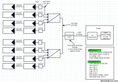
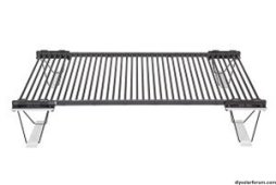
I have a number (~150) of 10 year old, ground mount Solyndra SL-200-200 panels that we want to use for grid-tied PV. These sit on feet that clip onto the panels and support them about 12 inches off the ground. I am working in a large sunlit area to place these panels. However, there is approximately 225' from this panel area to the electrical service for the home. I plan on controlling the wiring costs by putting two GoodWe inverters near the panels. The inverters will be mounted by the solar panel field and their outputs will be connected through a 125 A panel (Aggregation Panel on the SLD). Then I want to bring AC over the 220' feet back to the house through a direct burial cable. The AC will connect to an AC disconnect near the meter and connect to the service in the house either through the box or a line side tap after we see if either the main panel or the sub-panel in the basement has the capacity.
I'm concerned about whether what I have in mind work, for example, will I have too large a voltage drop given the long AC run - and anything else that I probably didn't think of!
Thanks!!
Basics
Location - Philadelphia, Ground Mount
Usage - ~26000 kWh/yr (AC, large house, barn)
Goal - Grid-Tied for bill reduction
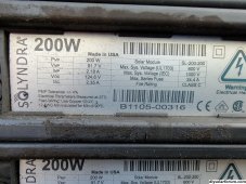
Panels (please see the Solyndra documents attached) -
(128) Solyndra SL-200-200 These panels are approximately ~10 years old
Voc: 124.6 Voc (on the panels I've tested I'm seeing 115 V)
Isc: 2.35 A
Pmp: 200 W
Vmp: 91.7 V
Imp: 2.18 A
Max System Voltage: 1000 V
Max Series Fuse: 24.4 A
Panel Array Sizing
I plan on combining the panels 4x4 (16 panels) - four panels per string and 4 strings per MPPT. I will use a junction box to combine the strings. Using all 8 MPPTs on the two inverters lets me use 128 of the best panels out the the 150 that I have.
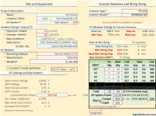
Inverters - (2) GoodWe GW9600A-MS
Max Output Power: 19,200W
Input Voltage Range: 80-600V
GoodWe has worked with me on the string sizing - their estimates are in the GoodWe image.

 en.goodwe.com
Combiner Boxes for the strings (Solar Combiner Box PV Combiner Box 4 String With15A Rated Current Fuse Solar DC Breaker Lightning Arreste and Solar Connector for Solar Power Systems10AWG Solar Cable)
Aggregation Panel (SIEMENS W0816ML1125CU 125 amp, 8 Space, 16 Circuit, Outdoor Center)
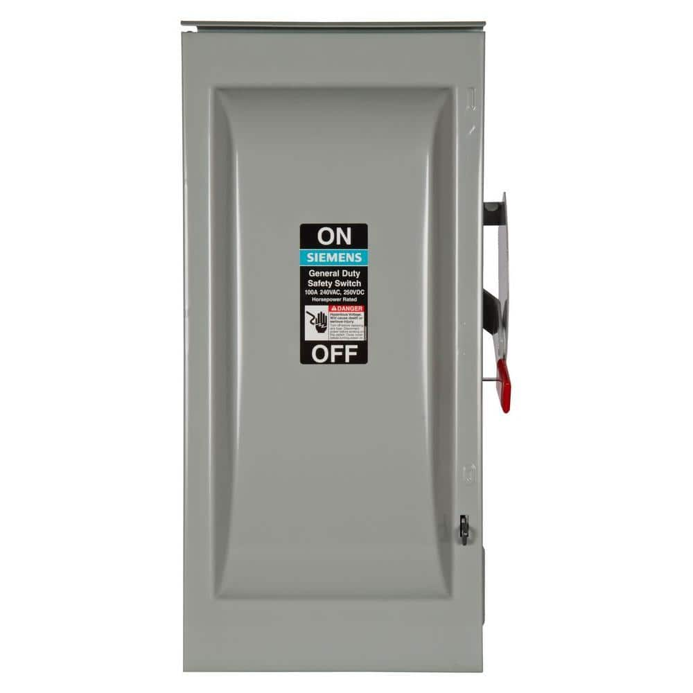
AC Disconnect -
Wiring -
Panels to Junction box - #10
Junction box to inverter - #10 THHN in 3/4" PVC
Inverters to aggregation panel - #8 THHN in 3/4" EMT
220' from Aggregation Panel to AC Disconnect 2-2-2-4 Direct Burial Cable
AC Disconnect to Line Side Tap (or box after closer inspection of the box)
I have a number (~150) of 10 year old, ground mount Solyndra SL-200-200 panels that we want to use for grid-tied PV. These sit on feet that clip onto the panels and support them about 12 inches off the ground. I am working in a large sunlit area to place these panels. However, there is approximately 225' from this panel area to the electrical service for the home. I plan on controlling the wiring costs by putting two GoodWe inverters near the panels. The inverters will be mounted by the solar panel field and their outputs will be connected through a 125 A panel (Aggregation Panel on the SLD). Then I want to bring AC over the 220' feet back to the house through a direct burial cable. The AC will connect to an AC disconnect near the meter and connect to the service in the house either through the box or a line side tap after we see if either the main panel or the sub-panel in the basement has the capacity.
I'm concerned about whether what I have in mind work, for example, will I have too large a voltage drop given the long AC run - and anything else that I probably didn't think of!
Thanks!!
Basics
Location - Philadelphia, Ground Mount
Usage - ~26000 kWh/yr (AC, large house, barn)
Goal - Grid-Tied for bill reduction
Panels (please see the Solyndra documents attached) -
(128) Solyndra SL-200-200 These panels are approximately ~10 years old
Voc: 124.6 Voc (on the panels I've tested I'm seeing 115 V)
Isc: 2.35 A
Pmp: 200 W
Vmp: 91.7 V
Imp: 2.18 A
Max System Voltage: 1000 V
Max Series Fuse: 24.4 A
Panel Array Sizing
I plan on combining the panels 4x4 (16 panels) - four panels per string and 4 strings per MPPT. I will use a junction box to combine the strings. Using all 8 MPPTs on the two inverters lets me use 128 of the best panels out the the 150 that I have.
Inverters - (2) GoodWe GW9600A-MS
Max Output Power: 19,200W
Input Voltage Range: 80-600V
GoodWe has worked with me on the string sizing - their estimates are in the GoodWe image.
GoodWe A-MS Series 5-9.6 kW Split Phase Up to 4 MPPTs Solar Inverter
GoodWe A-MS is 5-9.6 kw split phase up to 4 mppts solar inverter, which is designed to meet the safety regulations of the American market, including Arc Fault Circuit Interrupter and Rapid Shutdown. Click to learn more about GoodWe A-MS Series split phase grid tie solar inverter.
Combiner Boxes for the strings (Solar Combiner Box PV Combiner Box 4 String With15A Rated Current Fuse Solar DC Breaker Lightning Arreste and Solar Connector for Solar Power Systems10AWG Solar Cable)
Aggregation Panel (SIEMENS W0816ML1125CU 125 amp, 8 Space, 16 Circuit, Outdoor Center)
AC Disconnect -
Siemens General Duty 100 Amp 240-Volt 2-Pole Outdoor Fusible Safety Switch with Neutral GF223NR - The Home Depot
General Duty Safety Switches are intended for applications where reliable performance and continuity of service are needed, but where duty requirements are not severe and usual service conditions prevail.
www.homedepot.com
Wiring -
Panels to Junction box - #10
Junction box to inverter - #10 THHN in 3/4" PVC
Inverters to aggregation panel - #8 THHN in 3/4" EMT
220' from Aggregation Panel to AC Disconnect 2-2-2-4 Direct Burial Cable
AC Disconnect to Line Side Tap (or box after closer inspection of the box)
Attachments
-
 2022-05-20 08.41.28.jpg1.6 MB · Views: 8
 -
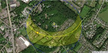 2023-09-01_10-33-01_SunPath.jpg414.4 KB · Views: 7
 -
GW_A-MS_Datasheet-EN.pdf507.8 KB · Views: 5
-
pdfslide.net_designguide-200series-solyndra.pdf3.9 MB · Views: 2
-
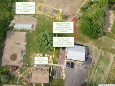 SiteDiagramR2.jpg638 KB · Views: 7
 -
 SLD.jpg602.6 KB · Views: 8
 -
 Solyndra-SL-200-200-2.jpg22.9 KB · Views: 10
 -
 GoodWeA-MS9600_calcs.png87.6 KB · Views: 14