


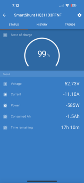
Just finished a small test project with a ESP32 Devkit and MCP2515 CANBUS module following the instructions at the below post on the forum. In short, YES!, the Victron Shunt is reporting SOC%, Voltage, Current, and other items to the EG4 6000xp and controlling charge/discharge/etc. Thanks to the members in that thread for the core work done before. I'm using LFP Battery and Battery #02 (Pylontech) on the 6000XP.
And yes I converted a Lynx Power-In with M8 bolts and mega fuses.
Simply wanted the shunt to report this information regardless of what type of DIY batteries I have behind it, in my case EVE 105s. Now I need to make a real PCB for it and a case.
Link: https://diysolarforum.com/threads/d...hunt-to-inverter-integration-solis-etc.44750/
Here is some cool pics of it working and some serial output from ESP:


Serial Output from ESP:
[ 1056][main.cpp:113] UpdateCanBusData(): Battery Voltage Update: 52822V
[ 1059][main.cpp:119] UpdateCanBusData(): Battery Current Update: -11673mA
[ 1066][main.cpp:125] UpdateCanBusData(): Battery SOC Update: 995%
[ 1072][main.cpp:196] loop(): Sending Switch Update Data
[ 1128][CANBUS.cpp:60] SendAllUpdates(): Sending all CAN Bus Data
[ 1129][CANBUS.cpp:304] SendParamUpdate(): Sent PYLONTECH String.
[ 1135][CANBUS.cpp:333] SendParamUpdate(): Inverter Parameters update via CAN Bus sent.
[ 1138][CANBUS.cpp:138] SendBattUpdate(): Inverter SOC Battery update via CAN Bus sent.
[ 1151][CANBUS.cpp:160] SendBattUpdate(): Inverter Battery Voltage, Current update via CAN Bus sent.
[ 1161][CANBUS.cpp:182] SendBattUpdate(): Inverter Protection / Alarm Flags via CAN Bus sent.
[ 1169][CANBUS.cpp:205] SendBattUpdate(): Battery Charge Flags via CAN Bus sent.
[ 1559][main.cpp:190] loop(): New block arrived; Value count: 17, serial 1
[ 2056][main.cpp:190] loop(): New block arrived; Value count: 13, serial 2
[ 2056][main.cpp:113] UpdateCanBusData(): Battery Voltage Update: 52819V
[ 2059][main.cpp:119] UpdateCanBusData(): Battery Current Update: -11682mA
[ 2066][main.cpp:125] UpdateCanBusData(): Battery SOC Update: 995%
[ 2176][CANBUS.cpp:60] SendAllUpdates(): Sending all CAN Bus Data
[ 2177][CANBUS.cpp:304] SendParamUpdate(): Sent PYLONTECH String.
[ 2183][CANBUS.cpp:333] SendParamUpdate(): Inverter Parameters update via CAN Bus sent.
[ 2186][CANBUS.cpp:138] SendBattUpdate(): Inverter SOC Battery update via CAN Bus sent.
[ 2199][CANBUS.cpp:160] SendBattUpdate(): Inverter Battery Voltage, Current update via CAN Bus sent.
[ 2209][CANBUS.cpp:182] SendBattUpdate(): Inverter Protection / Alarm Flags via CAN Bus sent.
[ 2217][CANBUS.cpp:205] SendBattUpdate(): Battery Charge Flags via CAN Bus sent.
[ 2561][main.cpp:190] loop(): New block arrived; Value count: 17, serial 3
[ 3058][main.cpp:190] loop(): New block arrived; Value count: 13, serial 4
[ 3058][main.cpp:113] UpdateCanBusData(): Battery Voltage Update: 52816V
[ 3060][main.cpp:119] UpdateCanBusData(): Battery Current Update: -11770mA
[ 3067][main.cpp:125] UpdateCanBusData(): Battery SOC Update: 995%
[ 3224][CANBUS.cpp:60] SendAllUpdates(): Sending all CAN Bus Data
[ 3225][CANBUS.cpp:304] SendParamUpdate(): Sent PYLONTECH String.
[ 3231][CANBUS.cpp:333] SendParamUpdate(): Inverter Parameters update via CAN Bus sent.
[ 3234][CANBUS.cpp:138] SendBattUpdate(): Inverter SOC Battery update via CAN Bus sent.
[ 3247][CANBUS.cpp:160] SendBattUpdate(): Inverter Battery Voltage, Current update via CAN Bus sent.
[ 3257][CANBUS.cpp:182] SendBattUpdate(): Inverter Protection / Alarm Flags via CAN Bus sent.
And yes I converted a Lynx Power-In with M8 bolts and mega fuses.
Simply wanted the shunt to report this information regardless of what type of DIY batteries I have behind it, in my case EVE 105s. Now I need to make a real PCB for it and a case.
Link: https://diysolarforum.com/threads/d...hunt-to-inverter-integration-solis-etc.44750/
Here is some cool pics of it working and some serial output from ESP:
Serial Output from ESP:
[ 1056][main.cpp:113] UpdateCanBusData(): Battery Voltage Update: 52822V
[ 1059][main.cpp:119] UpdateCanBusData(): Battery Current Update: -11673mA
[ 1066][main.cpp:125] UpdateCanBusData(): Battery SOC Update: 995%
[ 1072][main.cpp:196] loop(): Sending Switch Update Data
[ 1128][CANBUS.cpp:60] SendAllUpdates(): Sending all CAN Bus Data
[ 1129][CANBUS.cpp:304] SendParamUpdate(): Sent PYLONTECH String.
[ 1135][CANBUS.cpp:333] SendParamUpdate(): Inverter Parameters update via CAN Bus sent.
[ 1138][CANBUS.cpp:138] SendBattUpdate(): Inverter SOC Battery update via CAN Bus sent.
[ 1151][CANBUS.cpp:160] SendBattUpdate(): Inverter Battery Voltage, Current update via CAN Bus sent.
[ 1161][CANBUS.cpp:182] SendBattUpdate(): Inverter Protection / Alarm Flags via CAN Bus sent.
[ 1169][CANBUS.cpp:205] SendBattUpdate(): Battery Charge Flags via CAN Bus sent.
[ 1559][main.cpp:190] loop(): New block arrived; Value count: 17, serial 1
[ 2056][main.cpp:190] loop(): New block arrived; Value count: 13, serial 2
[ 2056][main.cpp:113] UpdateCanBusData(): Battery Voltage Update: 52819V
[ 2059][main.cpp:119] UpdateCanBusData(): Battery Current Update: -11682mA
[ 2066][main.cpp:125] UpdateCanBusData(): Battery SOC Update: 995%
[ 2176][CANBUS.cpp:60] SendAllUpdates(): Sending all CAN Bus Data
[ 2177][CANBUS.cpp:304] SendParamUpdate(): Sent PYLONTECH String.
[ 2183][CANBUS.cpp:333] SendParamUpdate(): Inverter Parameters update via CAN Bus sent.
[ 2186][CANBUS.cpp:138] SendBattUpdate(): Inverter SOC Battery update via CAN Bus sent.
[ 2199][CANBUS.cpp:160] SendBattUpdate(): Inverter Battery Voltage, Current update via CAN Bus sent.
[ 2209][CANBUS.cpp:182] SendBattUpdate(): Inverter Protection / Alarm Flags via CAN Bus sent.
[ 2217][CANBUS.cpp:205] SendBattUpdate(): Battery Charge Flags via CAN Bus sent.
[ 2561][main.cpp:190] loop(): New block arrived; Value count: 17, serial 3
[ 3058][main.cpp:190] loop(): New block arrived; Value count: 13, serial 4
[ 3058][main.cpp:113] UpdateCanBusData(): Battery Voltage Update: 52816V
[ 3060][main.cpp:119] UpdateCanBusData(): Battery Current Update: -11770mA
[ 3067][main.cpp:125] UpdateCanBusData(): Battery SOC Update: 995%
[ 3224][CANBUS.cpp:60] SendAllUpdates(): Sending all CAN Bus Data
[ 3225][CANBUS.cpp:304] SendParamUpdate(): Sent PYLONTECH String.
[ 3231][CANBUS.cpp:333] SendParamUpdate(): Inverter Parameters update via CAN Bus sent.
[ 3234][CANBUS.cpp:138] SendBattUpdate(): Inverter SOC Battery update via CAN Bus sent.
[ 3247][CANBUS.cpp:160] SendBattUpdate(): Inverter Battery Voltage, Current update via CAN Bus sent.
[ 3257][CANBUS.cpp:182] SendBattUpdate(): Inverter Protection / Alarm Flags via CAN Bus sent.
Attachments
Last edited:
") subscribed
subscribed 
