diy solar

diy solar

DIY Battery via Smart shunt to inverter integration (Solis etc)

sijones2010

New Member
Joined
May 31, 2021
Messages
100
Hi All,

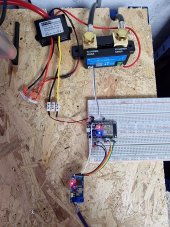
I've taken some code that handles Victron's VE.Direct protocol (Smart Shunt) and added in CAN Bus / PylonTech protocol connections, this allows the State of Charge, Voltage, Amps etc all be sent to the inverter - any one that supports the PylonTech protocol.

I have it connected to a Solis and works perfectly.

Secondly as it has MQTT I implemented commands that can be sent to enable and disable charging, and force charging, this I did so if solar isn't going to be good the following day (using Forecast Solar), then Home Assistant turns on the force charge and the inverter will charge the batteries, please note as per protocol it turns off at 97% SOC.

Currently I have a daly BMS on a 200amp battery pack, and a JKBMS on a 320Amp pack, tied together through the Victron Smart Shunt and it all works perfectly.

Code is here: https://github.com/sijones/VE.DirectMQTTCANBUS
 

Attachments

  • 20220806_205858.jpg
    20220806_205858.jpg
    277.8 KB · Views: 254
Last edited:
That is exactly what I am looking for - thank you for making it available! I also have a Solis Hybrid inverter and building a battery pack for it too. Just one question though about battery profiles that you use on the Solis...

I guess I will need to use the 'user define' profile to configure the voltages as I want for my battery (16 * LiFePO4 cells), but if I do that, does the Solis still accept and understand the pylontech data you send it via the CANbus? I'm sure I can't set the Solis to the Pylon battery profile or the voltages will all be wrong as I think the pylontech uses less cells. Thanks.
 
You can do either, use PylonLV in the Solis or User Defined, the software will send to the inverter the voltage to charge at and the current, in the config file there is init values.

#define initBattChargeVoltage 56000 // Battery Charge Voltage sent to inverter
#define initBattDischargeVoltage 45000 // Battery discharge voltage, not currently used
#define initBattChargeCurrent 100000 // in mA, this is just the initial / max setting, it will self adjust
#define initBattDischargeCurrent 100000 // in mA
#define initBattCapacity 475000 // used for charge limits when batteries becoming full.

I only use 56v to charge at and the batteries are able to handle the full 100Amp charge and discharge, if you want it to limit this then change it here and this will be used as a maximum.

The charge amp's is reduced at 90% SOC and then further at 95% to allow a balancer time to balance and try and keep run away cells going to high too fast, you don't want the BMS cutting off as this will trigger a error on the Solis of over voltage hardware.

The current reduction is initBattCapacity divide by 10 at 90%, then think it's divide by 18 at 95% - this am still adjusting to fine tune.

If you choose to use PylonTech protocol then you may see the charge/discharge enable/disable and force charge not work, am looking in to why, if you don't need this then you can enable PylonTech and it's straight forward to setup, otherwise use User Defined and disable PylonTech in the config file, it then uses a different method to control the inverter which is how I do it currently.
 
There is also a file which has the Home Assistant config for controlling the switches of the software, but also you'll see how to send the commands to it over MQTT.

There will be a newer version coming in a few weeks with more features etc, I've got more ideas to make it better.

Be careful with the Victron, it supposed to send the all data every second, but i find it send some data every second then after some time will swap the data sent every second, so at some points you'll find your not seeing SOC/Voltage/Current from the Victron.

On start up the software has to have had the SOC / Voltage and Current from the Victron to then start sending data to the Inverter, so if you see a delay on start up and think it's not working it will actually just be waiting for all data.

There is pictures of the wiring and I've tried to cover stuff in the Wiki.

I used Arduino IDE 2 for this version, but latest build is switching to Visual Code.

Once you've flashed the ESP32, there is over the air upgrade available so you don't need to plug it in again.
 
... but i find it send some data every second then after some time will swap the data sent every second, so at some points you'll find your not seeing SOC/Voltage/Current from the Victron.

This is all great information, thanks. But odd about the Victron... do you mean it swaps the order of the data it sends / sends different data / stops sending data at all?

How did you connect the Victron ve.direct connection to the arduino - it wasn't clear in the pics - looks like just the data lines with no ground reference?
 
Packets of data is sent every 1 second, but it's not everything, so I've seen H1 to H17 data sent for a while, then it will swap to send the Voltage, SOC, Current every second for a while. This to me is a bug by Victron but I can't report it to them as there seems to be no public support to go to.

I will fix this by implementing the hex protocol and asking for the SOC, Voltage and Current directly every x seconds.


New version no longer has this issue and is no longer relevant.

As you look at the smart shunt front on, it goes, Pin 1 live, Pin 2 TX, Pin 3 RX,Ppin 4 ground. Use your multi-meter to check what i say is ground has got continuity to the battery earth where you connect the battery to, then you know you have the right pin, it's 5v one end and ground on the other.
 
Last edited:
20220806_205931.jpg
 
Packets of data is sent every 1 second, but it's not everything, so I've seen H1 to H17 data sent for a while, then it will swap to send the Voltage, SOC, Current every second for a while. This to me is a bug by Victron but I can't report it to them as there seems to be no public support to go to.

I will fix this by implementing the hex protocol and asking for the SOC, Voltage and Current directly every x seconds.

As you look at the smart shunt front on, it goes, Pin 1 live, Pin 2 TX, Pin 3 RX,Ppin 4 ground. Use your multi-meter to check what i say is ground has got continuity to the battery earth where you connect the battery to, then you know you have the right pin, it's 5v one end and ground on the other.
Hello @sijones2010 .
Really appreciate the work you've done on this. I'm about to purchase a Victron BMV 712 to get your solution implemented with my 'unsupported' battery. Before i take the leap, was wondering if you've implemented any further fixes that you mentioned in the previous post?
 
Hi All,

I've taken some code that handles Victron's VE.Direct protocol (Smart Shunt) and added in CAN Bus / PylonTech protocol connections, this allows the State of Charge, Voltage, Amps etc all be sent to the inverter - any one that supports the PylonTech protocol.

I have it connected to a Solis and works perfectly.

Secondly as it has MQTT I implemented commands that can be sent to enable and disable charging, and force charging, this I did so if solar isn't going to be good the following day (using Forecast Solar), then Home Assistant turns on the force charge and the inverter will charge the batteries, please note as per protocol it turns off at 97% SOC.

Currently I have a daly BMS on a 200amp battery pack, and a JKBMS on a 320Amp pack, tied together through the Victron Smart Shunt and it all works perfectly.

Code is here: https://github.com/sijones/VE.DirectMQTTCANBUS
This is all FAB - many thanks!

Is there a quick way to test what the Smart Shunt's direction connection voltage is (should be getting mine shortly)?
 
Hi All,

I've taken some code that handles Victron's VE.Direct protocol (Smart Shunt) and added in CAN Bus / PylonTech protocol connections, this allows the State of Charge, Voltage, Amps etc all be sent to the inverter - any one that supports the PylonTech protocol.

I have it connected to a Solis and works perfectly.

Secondly as it has MQTT I implemented commands that can be sent to enable and disable charging, and force charging, this I did so if solar isn't going to be good the following day (using Forecast Solar), then Home Assistant turns on the force charge and the inverter will charge the batteries, please note as per protocol it turns off at 97% SOC.

Currently I have a daly BMS on a 200amp battery pack, and a JKBMS on a 320Amp pack, tied together through the Victron Smart Shunt and it all works perfectly.

Code is here: https://github.com/sijones/VE.DirectMQTTCANBUS
Also, is this 3.3V or a 5V voltage regulator in this Fritz Schematic - and any ideas where to purchase?

 
The ESP can take 5v directly on the Vin pin, it is a 5v regulator to give a wider input voltage range, I don't use that personally as I have a 48v to 5v module so i power all from the batteries. Best check the ESP32 board and see what voltage it accepts and then work out from there, you should be able to get a voltage regulator from ebay if needed.

If you have an oscilloscope, you'd be able to see the voltage signal used, but I just used a resistor divider, watched the serial port data for a while, it wasn't consistently correct and was corrupt ascii so took the resistors out and then it was fine. So use the resistor first and if that works perfect then leave it in.
 
Hi All,

I've taken some code that handles Victron's VE.Direct protocol (Smart Shunt) and added in CAN Bus / PylonTech protocol connections, this allows the State of Charge, Voltage, Amps etc all be sent to the inverter - any one that supports the PylonTech protocol.

I have it connected to a Solis and works perfectly.

Secondly as it has MQTT I implemented commands that can be sent to enable and disable charging, and force charging, this I did so if solar isn't going to be good the following day (using Forecast Solar), then Home Assistant turns on the force charge and the inverter will charge the batteries, please note as per protocol it turns off at 97% SOC.

Currently I have a daly BMS on a 200amp battery pack, and a JKBMS on a 320Amp pack, tied together through the Victron Smart Shunt and it all works perfectly.

Code is here: https://github.com/sijones/VE.DirectMQTTCANBUS
The pin connector on the Smart Shunt VE Direct port - any ideas where I can purchase just the pin header, as the Victron cables/accessory prices are a massive ripoff for what they achieve.

Found a short one on Amazon (right-angled) for a not too silly price in the end. Still only worth £4 in my view!
 
Last edited:
Back
Top