diy solar

diy solar

DIY Battery with JBD BMS to Solis Hybrid inverter using Pylontech protocol.

MJC55

New Member
Joined
Feb 16, 2023
Messages
7
Location
UK
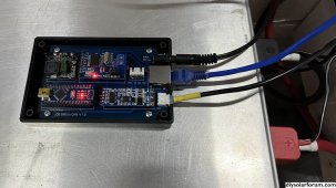
Simple Bridge between JBD BMS with a DIY Battery and Solis Hybrid inverter using Pylontech CAN bus protocol.

I have a DIY 16 cell LiFePO4 battery (about 4.5kWh). The BMS used is the JBD-SP25S003-L16S-100A. It was setup as a lead acid battery on my Solis inverter (RHI-3K-48ES-5G) and worked OK for 18 months, as long as you don't over discharge.
But I wanted to send the State of Charge (SoC) of the battery to the inverter to give greater control.

PROJECT HARDWARE
Arduino Nano, RS485 to UART module, MCP2515 CAN bus module and DC to DC converter.

I used the RS485 port on the BMS to get the following data: SoC, Voltage, Current and Temperature.
The data was then converted to PylonTech protocol, which could be read by the inverter.
MCP2515 module using the CAN bus library from coryjfowler, the only library I could get to communicate with Solis.
The Solis inverter was set up with the battery option "Pylon LV", nothing else needed to be done. The max. Voltage, max. Current and max. Discharge was set up in the code and send to the inverter.

Full Project see: github.com/martc55/jbd2solis
Image_Project.jpg
 
Last edited:
  • Like
Reactions: Cal
That's very neat hardware (y) May I ask where you got the PCB made and how much?

Does the RS485 port give more info than you could get from UART port? My JBD to Solis interface uses the UART port - no RS485 port on the Overkill version of the JBD.
 
Hi, I got the pcb’s from JLCPCB.COM for about £10 for 5 double sided boards.
But I went for cheapest delivery, so it took about 2 weeks.

As far as I know the RS485 and UART ports can give the same data from the BMS.
I did test my project without the RS485 module and connected it to the UART port and it worked fine.
Data from the BMS with be determined by the software. For example if you use the JBD Bluetooth
module you can get all the data and it can make changes the BMS values.
The Arduino code I use is only one way, I only use SoC, Volts, Current and Temperature.
Although it also gives, Cell max & min., 3 Temperature values, Mosfet charge & discharge and AFE error.
Hope this helps.
 
Thanks for the PCB info... I do 2 way via the UART, btw. I have some other feedback on your implementation - shall I post it here or do you prefer a PM?
 
Few random thoughts then, in no particular order... hopefully may be of interest?

a) What is the purpose of this code?
RSOC = (inInts[19]);
int deviation = RSOC + PSOC; // To reduce fluctuations in RSOC data
if (abs(deviation) <= maxDev){ // Maximum deviation of (default 250)
SOC = RSOC; // RSOC input, PSOC previous, SOC output
PSOC = RSOC;
}else{
SOC = PSOC;

I don't understand why you are adding the current and previous SOC value together, then ignore the current value if the addition of them exceeds 250. There shouldn't be fluctuations in SOC received from the BMS, not in the 15 months I've been using mine.

b) Do you use the ground on the CANBus? It would appear so from the schematic. I don't, but I had one module fail due to a voltage spike.

c) in CAN_bus.ino you have a number of lines like this...

CAN0.sendMsgBuf(0x359, 0, 7, CANData359); // Protection & Alarm flags
delay(5);
memset(0x359, 0, 7);

CAN0.sendMsgBuf(0x351, 0, 8, CANData351); // Battery voltage + current limits
delay(5);
memset(0x351, 0, 8);

The memset will write zero's to memory at location 359, with potentially unexpected results.
I suspect you meant to clear the CANData pointers instead, like this..
memset(CANData359, 0, 7);
but then that would overwrite the data that you don't regularly set. So, I'm puzzled what the memsets are for.

d) Had you thought about dynamically changing the charge current as the SOC exceeds 90/95%? I guess you've looked at @sijones2010's Solis interface code where he does that - I extended that concept in my implementation to also vary charge current based on temp, as I mentioned in this post..

e) Similarly, now you have control of the CAN data going to the Solis you could implement a force charge (e.g. charge up at night at cheap rate) by telling the Solis the SOC is below your 'forceChargeSOC' value (15% in your case).

I guess, like all of us, the code is a work in progress, but if you add WiFi connectivity to the project you could then add OTA support for ease of updating the software.

Anyway, just a few thoughts, I'm sure you've already thought of them.

As I said it's nice with the PCB... and I spotted the SCL/SDA header for a future IC2 display I guess :)
 
Hi, I will try to answer your questions. Please take on board I am not an expert programmer.

a) In another project where I used the BMS UART port and connected it to ESP32 with a 2.8” TFT display and Blynk.
I noticed that the SoC value fluctuates, so I built this safe guard into the code.
I could delete this part of code and test it. May be the fluctuations could be the display or something else?
But any suggestions to improvements this code would be appreciated.

b). CAN bus, I connected the ground from the project to pin 2 on the RJ45 cable going to the inverter.
I don’t think I need it, cos it works without it. But I read that if it not connected it could give an inverter fault.

c) I tried several CAN bus libraries, and some with ESP32, and the only one that communicates with Solis
Is the library from coryjfowler. But there was a problem, it could not send all 6 message every second.
So, this was my way to clear the buffer after every message. I will try your suggestion.

d & e). This is great for future development, but my initial self brief was to kept it simple and must be reliable.

I did add a connection on the PCB to an OLED display, initially I had problem’s so I removed it from the code to sort out later.

Hears a problem for you, when the battery was connect as a lead acid option for about 18 months, every 2 - 4 weeks I got a AFCI fault.
Since I connected the CAN bus no AFCI faults. Not changed any cables or connectors. Hope it continues that way.

Thanks for your comments,
 
Hi. I interested in your project did use a ESP32 and a MCP2515? cos I could not get to work with coryjfolwer library.
So I would be interested in what CAN bus library you used.
I will try your suggestions and let you know the outcome.
 
Hi, I will try to answer your questions. Please take on board I am not an expert programmer.
(y)

I noticed that the SoC value fluctuates, so I built this safe guard into the code.
Fluctuates in what way and by how much? I'm wondering if there were some data errors being received as I always get consistent SOC values (and I log them every 5s to my emonPi, so can see they have been working correctly for > 15 months).

If you do find you need to filter the SOC (though I think you won't need to), the logic you have won't do that.

The logic you have is to add the current and previous SOC values (which should all be between 0 and 100) and then only excluding values where the absolute value of the sum of those two values is > 250. This will never trigger unless you are getting SOC values that are greater than 125 or less than -125.

But any suggestions to improvements this code would be appreciated.
Sure... delete it ;)

c) I tried several CAN bus libraries, and some with ESP32, and the only one that communicates with Solis
Is the library from coryjfowler. But there was a problem, it could not send all 6 message every second.
My implementation, derived from @sijones2010's code also uses the coryjfowler ESP32 CANBus library for the MCP2515 controller.

d & e). This is great for future development, but my initial self brief was to kept it simple and must be reliable.
(y)

I did add a connection on the PCB to an OLED display, initially I had problem’s so I removed it from the code to sort out later.
If you want to keep it simple, yet still have a display, you could just add a 20x4 LCD alphanumeric screen via IC2. This is what I have done - it's a bit 1990's tbh, but it's all I needed to show basic info.

Hears a problem for you, when the battery was connect as a lead acid option for about 18 months, every 2 - 4 weeks I got a AFCI fault.
Since I connected the CAN bus no AFCI faults. Not changed any cables or connectors. Hope it continues that way.
I'm not convinced how good the Solis AFCI is with relation to false triggers - my RHI triggered when I got grid overvoltage conditions on the ac side (since resolved). The AFCI is configurable for sensitivity and switch-offable, but sounds like that is not an issue now.

I interested in your project did use a ESP32 and a MCP2515? cos I could not get to work with coryjfolwer library.
So I would be interested in what CAN bus library you used.
Sure - see Simon's code on github, via the thread linked below. I've heavily modified the code (not least to interface with the Overkill UART library rather than Victron SmartShunt and added a ton of extra control / MQTT / display / config and web interface), but the basic CANBus sending code and coryjfowler library is the same.

 
  • Like
Reactions: Cal
Thanks for the info, it was very useful. I think I got my work cut out for future.(y)
 
Simple Bridge between JBD BMS with a DIY Battery and Solis Hybrid inverter using Pylontech CAN bus protocol.

I have a DIY 16 cell LiFePO4 battery (about 4.5kWh). The BMS used is the JBD-SP25S003-L16S-100A. It was setup as a lead acid battery on my Solis inverter (RHI-3K-48ES-5G) and worked OK for 18 months, as long as you don't over discharge.
But I wanted to send the State of Charge (SoC) of the battery to the inverter to give greater control.

PROJECT HARDWARE
Arduino Nano, RS485 to UART module, MCP2515 CAN bus module and DC to DC converter.

I used the RS485 port on the BMS to get the following data: SoC, Voltage, Current and Temperature.
The data was then converted to PylonTech protocol, which could be read by the inverter.
MCP2515 module using the CAN bus library from coryjfowler, the only library I could get to communicate with Solis.
The Solis inverter was set up with the battery option "Pylon LV", nothing else needed to be done. The max. Voltage, max. Current and max. Discharge was set up in the code and send to the inverter.

Full Project see: github.com/martc55/jbd2solis
View attachment 179176
That's really cool, and exactly what I need! How easy/hard would it be to change it to use the JK-BMS protocol instead of JBD? (my bms is a JK).
 
This is great, thanks for sharing your code. Would you be able to share your PCB design files too please?
 
Back
Top