diy solar

diy solar

Pylontech battery in parallel with DIY Battery

marky0

New Member
Joined
Apr 24, 2022
Messages
36
Location
UK
I currently have three US5000 pylontech batteries working great with a Solis Hybrid inverter.
They are not quite big enough for daily use, particularly in winter when I charge them overnight to run the home during the day.
So thinking about upgrading by putting together a 15S pack of LF280K with a JK-BMS as I'll get an extra ~13kWh for the cost of one additional 4.8kWh US50000.
15S to match the 15S configuration of the pylontech packs so they will charge and discharge in balance.

But the question comes down to if the system will get confused if I leave the CAN bus interface connected between the inverter and pylontech batteries ? The idea being that I attach the DIY pack in parallel with the pylontech batteries under private supervision from the JK-BMS, and leave the pylontech pack to do any necessary communications with the inverter through CAN. The inverter nor pylontech pack will not know that the DIY pack exists. If the DIY pack gets in trouble it will disconnect through the JK-BMS.

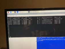
I've spent the last few days eavesdropping on the CAN bus between inverter and pylontech to test the idea, but can't quite work out who is the master. Inverter or battery.
The pylontech protocol doesn't appear to be clear on this point.
For example :

I set my inverter to charge the pylontech at 11:30pm every night.
I see the pylontech report to the inverter a change in the expected charge current when charging commences actioned from the inverter.
However, at 5am when the pylontech is fully charged, I see the pylontech report a gradual reduction in charge current as it nears 100%. But is this commanded by the battery or actioned by the inverter when it sees the battery nearing 100% SOC ?

Running the DIY pack in parallel with the pylontech will cause ~50% of charge current to be shared between pylontech and DIY pack.
So am I at risk here of the Solis inverter detecting a charge current that does not then tally with that reported from the pylontech CAN bus and the system throwing an error ?

Has anyone got any detailed experience of the pylon CAN bus to know whether this idea of adding a dumb pack in parallel is a non starter. Or will I need a babel fish to fuse the current data between pylontech and JK-BMS into a single coherent CAN bus stream to get this to work ?
 
I run two factory rack packs and five DIY packs.
The inverters don't seem 'smart' enough to know the Ah don't add - at least the MPP's aren't.
I had no issues running multiple times the Ah in DIY packs parallel with the comms packs, then during early 2023 I bought a Victron 500A smart shunt, and this made controlling the ESS far easier and better, due to accuracy of the SOC. I rely on Solar Assistant to pull all the info into one place and keep everything running smoothly. Comms are not my forte' there are some threads dedicated to exactly this topic - do a search maybe you will see something that helps.
 
In communications with the battery and inverter, inverter is the master.

For example, with Pylon, the inverter would send a query to CAN ID 4200, which is know as a ensemble request, the battery would respond with 4210 which provides pack voltage, current temperature, SOC and SOC. There are two widely used Pylon protocols, one is low voltage and the other is high voltage, the example I gave is for HV and used by many manufactures.

Also here is a really good reference in addition to the first link, between the two one can get most HV inverters on the market to talk CAN with DYI
 
For 48V, it is a 16S not 15S.
There are not usually any problems with different-sized packs, they will handle load/charge proportionately relative to their capacity. This is observable when watching the BMS' at work. If you use EndAmps/TailCurrent with the solar equipment, and you have 100AH & 280AH side x side a 10A EndAmp/TailCurrent is reasonable. 100AH = 5A while 280AH = 14A so you kinda have to split that to find the sweet spot. A GOTCHA, If endamps is too low, then you will experience HVD scenarios.

BMS is important, Pylontec is widely supported \\yay// and not there are other BMS' that support the Pylontec stack. The new JKBMS Inverter Edition does support Victron now, I believe Pylontec as well as a few others with more in the works. Alternately, Seplos, Pace also support Pylontec I believe, there may be others like TDT but don't go there. I myself am replacing my current fleet of JKBMS and building 3 more new packs with the latest JK Inverter editions. All to be fed to a Raspi W CAN, RS485 MODbus from Samlex & Midnite SCC's. sinally gonna be "nice & tidy" ;-)
 
There is no technical reason a 16s and Pylontech 15s can't be in parallel with one caveat, you must charge to the 15s profile. There will be some capacity not used, on the other hand the 16s will last much longer , more cycles.
 
Ahh yes, just looked it up, Pylontech are 15S to make exactly 48V. That would be quirky, best to stick with 15S if that's how the rest are.
It means correcting 48V/280AH - 13,440Wh / 13.4kWh
 
My 2p worth...

a) I'd stick with 15S architecture to match the voltages on the Pylontechs. Pylon uses pouch cells rather than prismatic, but AFAIAA that won't matter.

b) The battery pack will just send the relevant CAN bus messages to the Solis, about once a second. The Solis will just receive the data - it doesn't need to request data like it does on the RS485 meter port, for example.

However, at 5am when the pylontech is fully charged, I see the pylontech report a gradual reduction in charge current as it nears 100%. But is this commanded by the battery or actioned by the inverter when it sees the battery nearing 100% SOC ?
By the battery. The battery will request the charge rate in the CANBus message 0x351. This will be a result of both battery SOC and temperature.

I think I already gave you that info in my posting to you here...

Running the DIY pack in parallel with the pylontech will cause ~50% of charge current to be shared between pylontech and DIY pack.
Yes, which is not ideal.

So am I at risk here of the Solis inverter detecting a charge current that does not then tally with that reported from the pylontech CAN bus and the system throwing an error ?
No, the Solis will attempt to charge at the requested rate from the battery pack, that's all.

Has anyone got any detailed experience of the pylon CAN bus to know whether this idea of adding a dumb pack in parallel is a non starter. Or will I need a babel fish to fuse the current data between pylontech and JK-BMS into a single coherent CAN bus stream to get this to work ?
The issues are as @Steve_S mentioned in that charge rate will be too low... the pylontechs will be telling the solis what rate to charge at, which the Solis will deliver, but the individual batteries will only receive half that rate as the current will be shared across your DIY pack and the 3x pylons.

Far better to deploy a MITM solution to resolve exactly that issue, like Simon did using a Victron smart-shunt to Solis CAN interface as detailed in this thread (and similar to what @OffGridForGood mentioned above)...

 
For 48V, it is a 16S not 15S.
There are not usually any problems with different-sized packs, they will handle load/charge proportionately relative to their capacity. This is observable when watching the BMS' at work. If you use EndAmps/TailCurrent with the solar equipment, and you have 100AH & 280AH side x side a 10A EndAmp/TailCurrent is reasonable. 100AH = 5A while 280AH = 14A so you kinda have to split that to find the sweet spot. A GOTCHA, If endamps is too low, then you will experience HVD scenarios.

BMS is important, Pylontec is widely supported \\yay// and not there are other BMS' that support the Pylontec stack. The new JKBMS Inverter Edition does support Victron now, I believe Pylontec as well as a few others with more in the works. Alternately, Seplos, Pace also support Pylontec I believe, there may be others like TDT but don't go there. I myself am replacing my current fleet of JKBMS and building 3 more new packs with the latest JK Inverter editions. All to be fed to a Raspi W CAN, RS485 MODbus from Samlex & Midnite SCC's. sinally gonna be "nice & tidy" ;-)
Pylontech batteries are 15s batteries steve
 
The battery will request the charge rate in the CANBus message 0x351
Thanks @SeaGal that was the critical bit of information I was missing. For some reason I got it into my head that the solis inverter would be using the measured battery current reported in CAN message 0x0356, but it makes perfect sense that it would use the maximum limits reported in CAN message 0x0351. Doh !

So to close this all off, these are the CAN bus logs taken from a charge session to 100% on my system last night, incase anyone else on the forum might find them useful (3xUS5000C with a solis RHI-6K-48ES-5G-DC).
CAN bus Log.png
As the SOC (CYAN) and battery voltage (ORANGE) rise , the Max Charge Current (GREY) appears to command the solis charge current (YELLOW) to drop between 05:12AM and 05:15AM. Why exactly the solis or pylontech doesn't stop the charge cycle around 05:14AM when the battery voltage exceeds the Max charge voltage (BLUE) who knows, but it clearly kicks in at 05:17AM (but no CAN bus alarms in any of the registers are reported, so the pylontech's are perfectly happy with this approach).
Its interesting to note that the pylontech reports an SOC of 96% at 05:17AM and it takes a few minutes of zero charge current before reporting 100% SOC at 05:19AM. Only at that point does it reset "charge enable" in CAN message 0x035c, but the solis has decided to stop charging well before that point at 05:17AM.....

So not exactly what I was expecting, and there still seems to be some other mysterious logic going on under the hood.
But that is rabbit hole I am going to steer well clear of ! Thanks to all of your responses, seems I can parallel a DIY pack to my existing system with confidence and I won't mess anything up !
 
Last edited:
there still seems to be some other mysterious logic going on under the hood.
That's one reason I like to DIY stuff. I designed the logic that controls my battery ;)

But great graph and it's all working (y)
 
Thanks @SeaGal that was the critical bit of information I was missing. For some reason I got it into my head that the solis inverter would be using the measured battery current reported in CAN message 0x0356, but it makes perfect sense that it would use the maximum limits reported in CAN message 0x0351. Doh !

So to close this all off, these are the CAN bus logs taken from a charge session to 100% on my system last night, incase anyone else on the forum might find them useful (3xUS5000C with a solis RHI-6K-48ES-5G-DC).
View attachment 189370
As the SOC (CYAN) and battery voltage (ORANGE) rise , the Max Charge Current (GREY) appears to command the solis charge current (YELLOW) to drop between 05:12AM and 05:15AM. Why exactly the solis or pylontech doesn't stop the charge cycle around 05:14AM when the battery voltage exceeds the Max charge voltage (BLUE) who knows, but it clearly kicks in at 05:17AM (but no CAN bus alarms in any of the registers are reported, so the pylontech's are perfectly happy with this approach).
Its interesting to note that the pylontech reports an SOC of 96% at 05:17AM and it takes a few minutes of zero charge current before reporting 100% SOC at 05:19AM. Only at that point does it reset "charge enable" in CAN message 0x035c, but the solis has decided to stop charging well before that point at 05:17AM.....

So not exactly what I was expecting, and there still seems to be some other mysterious logic going on under the hood.
But that is rabbit hole I am going to steer well clear of ! Thanks to all of your responses, seems I can parallel a DIY pack to my existing system with confidence and I won't mess anything up !
How do you get this graph? is it coming from your inverter or do you have something elese that can interpret the CAN bus? Thanks
 
Has anyone got any detailed experience of the pylon CAN bus to know whether this idea of adding a dumb pack in parallel is a non starter. Or will I need a babel fish to fuse the current data between pylontech and JK-BMS into a single coherent CAN bus stream to get this to work ?
From what i have learnt, with CAN, the inverter is passive and just listens. The BMS sends periodic messages, so the inverter just needs to know which protocol to expect. The requirements seem to be only 2 things; correct protocol set on the inverter, and messages arrive in a timely manner. We've had issues with the inverter panicking if a message is missed.

I've done exactly what you are suggesting - put additional (non-comms) batteries on the 'end' of the chain, and the comms-capable batteries don't know anything about the extra batteries. We also do this when testing new batteries/BMSs - chain up a dozen of them (with power cables), but only have the RS485 cables joining the master and 2nd battery, then 3rd, then 4th, etc until you have tested that the BMS on the master battery is truly capable of talking to that many batteries in a chain.

The inverter doesn't know, or need to know about the non-comms batteries, and the only issue is that the master battery is (probably) polling the 2nd, 3rd, 4th comms-capable batteries for their current request (probably over rs485), adding it all up and telling the inverter (over the CAN connection). The problem you *might* get is that say batteries 1(master), 2, 3, 4 are at 99%, all these batteries request say 1A each, so the inverter only sends 4A, but non-comms batteries 5, 6, 7, 8 are wanting 25A each, and get a much slower charge. At the end of the day, this will probably not make much difference, and it will depend on how aggressive your comms batteries are. I've seen firmware for PACE BMS's that ask for full current (100A) all the way to 100%, and other firmwares where the taper-off graph is very smooth, starting from ~95%. At the end of the day, if your non-comms slow right down at 95% and get a bit starved, its probably going to extend their life *unless* you really need that 98,99,100 percent time to do balancing.
 
In communications with the battery and inverter, inverter is the master.

For example, with Pylon, the inverter would send a query to CAN ID 4200, which is know as a ensemble request, the battery would respond with 4210 which provides pack voltage, current temperature, SOC and SOC. There are two widely used Pylon protocols, one is low voltage and the other is high voltage, the example I gave is for HV and used by many manufactures.

Also here is a really good reference in addition to the first link, between the two one can get most HV inverters on the market to talk CAN with DYI
Hey Solar Guppy I’m late to the party but I’m in deep now. I have 3 Sonnen Batteries that have Pylontech BMS’s in them. This has force me to learn about Can Bus. I did all the YouTube watching, I know raspberry pi python programming very well so I bought the 2515 HAT to fit on the Rasberry pi so I can read CAN bus. And I can do that no problem. Just wondering if anybody created an index of what all the pylontech can id’s are and how to interpret the data. Since you talked about 4200 and 4210 I went straight to them and got the data. Have not a clue what it means.
 

Attachments

  • IMG_3360.jpeg
    IMG_3360.jpeg
    251.8 KB · Views: 7
Just wondering if anybody created an index of what all the pylontech can id’s are and how to interpret the data.

If you are going to be sniffing the CANBus data, this is the info you should be seeing...

Message ID and contents..
0x351: Charge and Discharge parameters
= (max charge voltage, charge current, discharge current, discharge voltage (the latter is not used by Solis))
0x355: SOC & SOH
0x356: Current measurement of Battery Voltage, Current & Temp
0x359: Protection & Alarm flags
0x35C: Battery charge request flags (which I heard are ignored by Solis; I don't use them)
0x35E: Manufacturer name ("PYLON ") = ASCII "PYLON" followed by 3 spaces.
Thanks SeaGal, I will focus on those CanBus ID’s.
 
Back
Top