diy solar

diy solar

Solis Hybrid Inverter Charging Parameters with a Pylontech battery

marky0

New Member
Joined
Apr 24, 2022
Messages
36
Location
UK
I've been doing a deep dive into my pylontech battery (three US5000 connected in parallel to a solis RHI-6K-48ES-5G-DC hybrid inverter). I had always assumed that the pylontech battery would communicate the correct charge voltage settings to the inverter through the CAN bus. But I am now not sure this is the case. Before I start playing with my inverter settings I am seeking some feedback to see if anyone else has gone down this rabbit hole ! :geek:

On the inverter under Advanced Settings : Storage Energy Set : Control Parameters is the following screen
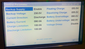
Untitled.png

First observation is that the Battery Overvoltage and Undervoltage look well wrong.
Pylontech running 15 cells with a max voltage of 3.6v per cell should make the overvoltage = 54v, certainly not 60V ! and the pylontech manual says that the battery min voltage should be 44.5v
Probably not of a huge concern as the battery BMS will kick in its own protection if the correct values are exceeded, but just surprised these are wrong in the inverter. Clearly the CAN bus is not setting them!

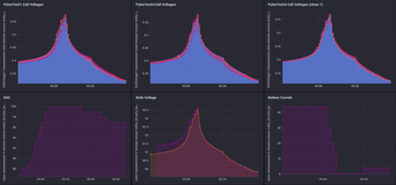
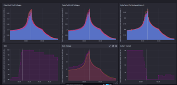
More interestingly I have connected to the RS485 port on the master US5000 battery to log the cell voltages during a typical charge cycle to 100% and see the following
Untitled.png

I have ~80mV imbalance across all the cells in each of the three battery packs which isn't bad, but the Solis inverter doesn't appear to be entering a float voltage state of 53.5v for any period of time to allow the BMS to balance the packs ????? I can only guess that the float voltage of 53.5v (3.56v/cell) is very close to the likely 3.6v cell limit in the pylontech BMS. Some cells seem to be very close to 3.6v which could then be triggering a charge shutdown to the inverter through the CAN bus and cutting short any float mode. This indicates to me that the float voltage is set too high and needs to be reduced to at least 53v if not 52.5v to allow the BMS balancer to have time to balance the pack (and with only a reported 50mA balancer in the pylontech BMS this needs a good few hours !)

Charge shut-down and over voltage protection is not reported through RS485 and I haven't got a CAN bus reader to verify this hypothesis (one is on order !). But I had expected that the pylon battery to control the charge voltage through the CAN link but this doesn't appear to be the case, unless this is the expected operation but it doesn't look right to me. Seems that the battery could get out of balance over prolonged use with these settings.

Before I start playing with the inverter parameters has anyone got any detailed experience of the pylontech/solis charge/balancing cycle ?
Are these the results I should be expecting ?
Thanks in advance
 
Last edited:
Please confirm that I'm seeing all 15 cells at or above 3.50V with a peak voltage of about 53.5V.

If that's the case, the cells are relatively well balanced, and they don't need any more.

Note that the inverter settings are independent from the battery settings. The settings screen is not updated with the battery communicated values, and any changes will be overridden by the BMS.

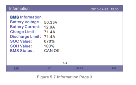
In the information section of the inverter menu, do you see BMS information?

From the manual:

1703039823796.png

Have you selected "Pylon" in the battery select menu?
 
As @sunshine_eggo has said:-
- it all looks good and
- I also see that all cells are >3.5 when 100% is reported which is good.
- I agree that the 'control parameter' screen is next to useless and look at page 3/4 of the info screen for the live data fed back to the Solis from the Pylontech.

I have a Solis RHI same as yours, but with DIY battery pack, so I am using the user-defined battery settings from which I can set the Solis over & under voltage setting - IIRC, you can't set those manually when you select PylonLV as your battery type, but that shouldn't matter - as you say the Solis would never charge at a voltage higher than what the Pylontechs tell it to charge at and you have the protection of the BMS anyway.

AFAIAA there is no message in the pylon protocol to tell the inverter what to set the inverter's over and under voltage protection to... Instead, the pylon will tell the Solis what (max) voltage to charge at, together with the charge and discharge currents.

This is clearly working as expected in your graphs. You can see that the Pylon's are starting with a 40A charge, then reduce that in steps of 30A, 25A, 20A, 15A and 5A as the SOC nears 100%. It is during that time of reduced charge that most of the balancing will take place. e.g. when voltage is above 'x' and they are being charged, but current is reduced. That is exactly the same algorithm I use in my DIY control software, although I charge at a lower rate for longer.

You say...
I had expected that the pylon battery to control the charge voltage through the CAN link but this doesn't appear to be the case, unless this is the expected operation but it doesn't look right to me.
...this is almost true, the pylon will send max voltage and specify a current. Hence the Solis will raise its charge voltage to achieve the requested charge current, without exceeding the max voltage requested. Obviously the actual voltage that the Solis will generate will depend on the voltage of the batteries at any given point in time and the resistance of your cables between inverter and batteries.

If you are going to be sniffing the CANBus data, this is the info you should be seeing...

Message ID and contents..
0x351: Charge and Discharge parameters
= (max charge voltage, charge current, discharge current, discharge voltage (the latter is not used by Solis))
0x355: SOC & SOH
0x356: Current measurement of Battery Voltage, Current & Temp
0x359: Protection & Alarm flags
0x35C: Battery charge request flags (which I heard are ignored by Solis; I don't use them)
0x35E: Manufacturer name ("PYLON ") = ASCII "PYLON" followed by 3 spaces.
 
Thanks for your replies !
I confirm I have the PYLON LV protocol set correctly and everything is OK on the information screen.
It is possible to change all the settings on the control parameters screen (float, equalizing, over, under voltage) even when PYLON LV battery is set, but I haven't yet tested if they do anything.

But I am still unsure about the measured charge data in my original post.
Andy from the off grid garage has done a very good video on LFP charging, its 30mins but is really worth a watch
As far as I understand its important to carry out the following three charging stages
STAGE 1 : Bulk Charge : Constant current charge the pack to ~3.55v per cell (53.25v for a 15S pylon pack)
STAGE 2 : Absorption Charge : Constant voltage charge the pack until the current drops to a low level to fully charge the pack
STAGE 3 : Float Charge : Drop the voltage slightly below STAGE 2 and allow the BMS balancer some time to equalize the cell voltages to balance the pack.

But this is clearly not what I see in the graphs from the original post. I only have STAGE 1. There are no constant voltage stages 2 and 3 ?
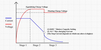
The solis technical website suggests that the control parameters are defined as follows

Untitled.png

So providing they work when PYLON LV battery is enabled, this says to me that equalizing charge should be set to 53.25v and float charge maybe to 53v. But why isn't this logic set through the CAN bus ? Before I start playing with the settings what am I missing ??
 
Before I start playing with the settings what am I missing ??
The documentation you refer to is for lead-acid, not LFP.

STAGE 1 : Bulk Charge : Constant current charge the pack to ~3.55v per cell (53.25v for a 15S pylon pack)
Personally, for cell longevity, I see little gain in charging that high. Yes, it may help with balancing, but that can be achieved by charging to 3.45V or 3.5V regularly. Obviously YMMV.

But, having said that, I'd just let the Pylontech's BMS do its stuff - it will tell the Solis what to charge to and at what rate - we already saw that it reduces charge current as the SOC goes above about 98%. If that's what Pylontech have decided is best for them to offer their 10 year warrantee (or whatever length it is), I'd just leave it be unless you have a specific problem to address.
 
Thanks for your replies !
I confirm I have the PYLON LV protocol set correctly and everything is OK on the information screen.
It is possible to change all the settings on the control parameters screen (float, equalizing, over, under voltage) even when PYLON LV battery is set, but I haven't yet tested if they do anything.

But I am still unsure about the measured charge data in my original post.
Andy from the off grid garage has done a very good video on LFP charging, its 30mins but is really worth a watch
As far as I understand its important to carry out the following three charging stages
STAGE 1 : Bulk Charge : Constant current charge the pack to ~3.55v per cell (53.25v for a 15S pylon pack)
STAGE 2 : Absorption Charge : Constant voltage charge the pack until the current drops to a low level to fully charge the pack
STAGE 3 : Float Charge : Drop the voltage slightly below STAGE 2 and allow the BMS balancer some time to equalize the cell voltages to balance the pack.

But this is clearly not what I see in the graphs from the original post. I only have STAGE 1. There are no constant voltage stages 2 and 3 ?
The solis technical website suggests that the control parameters are defined as follows

View attachment 184307

So providing they work when PYLON LV battery is enabled, this says to me that equalizing charge should be set to 53.25v and float charge maybe to 53v. But why isn't this logic set through the CAN bus ? Before I start playing with the settings what am I missing ??

The default Pylontech behavior is ONLY the CC and CV stages. Float is not done. In other words:

1) Charge to Voltage.
2) Hold this voltage until you can't any more.

In almost all cases, any changes you make to the voltages will be ignored. The BMS is controlling the system.

Personally, for cell longevity, I see little gain in charging that high. Yes, it may help with balancing, but that can be achieved by charging to 3.45V or 3.5V regularly. Obviously YMMV.

But, having said that, I'd just let the Pylontech's BMS do its stuff - it will tell the Solis what to charge to and at what rate - we already saw that it reduces charge current as the SOC goes above about 98%. If that's what Pylontech have decided is best for them to offer their 10 year warrantee (or whatever length it is), I'd just leave it be unless you have a specific problem to address.

+100
 
The documentation you refer to is for lead-acid, not LFP.
That's understood, but I couldn't find any documentation on the control parameters menu.
It doesn't even make sense that equalization and float voltages are on this menu when the inverter knows that an LFP battery connected. These are clearly lead-acid charge terms, but what you call them is frankly irrelevant. A better description would be whether the inverter is in constant current or constant voltage charge mode.
But I've just made the assumption that the definitions read across between the lead-acid menu and the control parameters menu.
 
Personally, for cell longevity, I see little gain in charging that high. Yes, it may help with balancing, but that can be achieved by charging to 3.45V or 3.5V regularly. Obviously YMMV.
As I understand it the academic literature is still debating whether there is a significant degradation of LFP at charge voltages unless they are greater 3.6v [Ref]. But high charge voltages are certainly not good for NMC !
But I think Andy will agree with you that there probably isn't much value charging much beyond 3.45v if you have a long absorption (constant voltage) second charge stage.
From the traces above, clearly pylontech are taking the approach of maximising the constant current charging phase to charge each cell to 3.6v, and not even bothering with absoprtion.
 
Last edited:
OK, so the results are in. I changed my inverter control parameters last night and left the pylon/inverter to do its thing.
Here is what I observed.
You can't set the "Equalizing Charge" below 54v on the inverter, and even when you do, upon saving the parameters it resets back to 55v. So either this logic is embedded within the solis inverter when you have the pylon battery set, or its being set through the CAN bus.
You can set the "Float Charge" to anything you like, but it does make any difference. Traces below for last nights charging with "Float Charge" set to 52.8v.
Untitled.png
Clearly no difference and that is perhaps unsurprising if the "Equalizing Charge" aka Charge Voltage at Constant Current is hard wired to 55v. The inverter will never get into a float mode as a cell will hit 3.6v well before the "Equalizing Charge" can ever be met.

So I think I've got to the bottom of the rabbit hole ! Clearly none of these control parameters do anything, and they are perhaps a few Easter eggs left by the solis engineers for some owners to waste their time with ! :LOL:
 
As I understand it the academic literature is still debating whether there is a significant degradation of LFP at charge voltages unless they are greater 3.6v [Ref].

There's no debate. LFP used to be charged to 4.2V and discharged to 2.0V to get an extra 10-15%. Unfortunately, they discovered that cycle life was horribly disappointing.

The industry response was to limit range from 2.5 to 3.65V losing that 10-15% of capacity but finally yielding the claimed cycle life.

There is much anecdotal evidence that charges to 3.45V further improve cycle life.

It's well known that charging to full is the most stressful portion of a typical cycle. Limiting the voltage and current at peak SoC appears to improve cycle life.

But high charge voltages are certainly not good for NMC !

Huh? Relative to LFP, "high" NMC voltages are fine. I charge to 3.92V/cell (75%) on my NMC bank.

But I think Andy will agree with you that there probably isn't much value charging much beyond 3.45v if you have a long absorption (constant voltage) second charge stage.

Yep. The only thing is you lose the fast charge benefit of LFP... still faster than lead acid, but the 3.45V limit means you need an actual absorption phase.

From the traces above, clearly pylontech are taking the approach of maximising the constant current charging phase to charge each cell to 3.6v, and not even bothering with absoprtion.

This is better behavior than some. It looks like they've refined the algorithm... it used to just hold the charge voltage until there wasn't sufficient PV. The complaint is likely to become that you're losing SoC even when PV is available.... no float.
 
Back
Top