diy solar

diy solar

Solis 3KW hybrid with DIY 16S LifePO4 battery bank, advice / sanity check

kipper

New Member
Joined
May 19, 2023
Messages
21
Location
South Yorkshire
OK, I'm about to order a Solis S5-EH1P-L 3KW hybrid inverter and batteries to replace my now defunct Sunny boy.

As for the battery I'm going to struggle to drag a 40Kg pylontech / Fogstar rack mount battery up into the loft and mount it to the inside of the gable end, however, I do like the idea of constructing my own LifePO4 pack as I've built several successful 10S5P Li-on E-bike battery packs as well as a LIfePo4 portable e-bike charger so have a good handle on what's required, this will mount very neatly to the wall.


Here is what I'm planning;

16 off EVE LF105 3.2V 105Ah prismatic cells in series giving 51.2V / 5KWh

JBD-SP25S003-L16S-100A BMS

Custom steel fire proof thermostatically heated box using silicone heater mats ( these work well on ebike batteries).


Existing PV array;

Pmax 1545W

Voc 273V

Vpm 227V

Ipm 5.13A


The inverter spec seems to be OK with the PV array.

I believe I need to set the inverter to lead acid as this is a dumb battery, for the charge Voltage I'm thinking 56V however I need to make sure this is below the over charge limit of the BMS or it will trigger an inverter fault if the BMS intervenes.

It looks like there is no way of setting an over discharge limit with a dumb battery (which is a bit surprising) so I'm looking at building a Can Bus / Arduino interface and use the Pylontech protocol although I haven't looked into this in detail yet, if I can get the basic system up and running I can add this at a later date.

Any thoughts welcomed.
 
I have lots of thoughts, as so similar to my setup :) . Before I detail them, do you have specific budgetary limits?
 
I'm looking at around £2000, about £1000 for the inverter and the rest for the battery. I do have 2 complete sunny boy inverters that I can sell to offset some of the cost but need to find a couple of substantial boxes to pack them in as they are incredibly heavy.

The main driver for this is having PV already installed on my roof and a heating-hungry workshop.

I was hoping someone had a similar setup.:)
 
Here's my 2p worth.. FYI I have 14.3kWh DIY battery, JBD BMS, Solis RHI 3.6kW and a new EH1P 6kW and custom ESP32 JBD to BMS hardware & software.

OK, I'm about to order a Solis S5-EH1P-L 3KW hybrid inverter and batteries to replace my now defunct Sunny boy.
YMMV, but I would recommend bigger inverter - almost no difference in price and has more future expansion options. 5 & 6kW versions can deliver 5kW from battery, rather than only 3kW from the 3kW & 3.6kW versions. Up to 3.6kW comes under G98 DNO notification after install, whereas above 3.6kW you will need G99 approval first, but that only took my DNO a week to respond to.

As for the battery I'm going to struggle to drag a 40Kg pylontech / Fogstar rack mount battery up into the loft and mount it to the inside of the gable end, however, I do like the idea of constructing my own LifePO4 pack as I've built several successful 10S5P Li-on E-bike battery packs as well as a LIfePo4 portable e-bike charger so have a good handle on what's required, this will mount very neatly to the wall.
I'm very happy I built a DIY battery pack :)

Here is what I'm planning;
16 off EVE LF105 3.2V 105Ah prismatic cells in series giving 51.2V / 5KWh
JBD-SP25S003-L16S-100A BMS
If you can stretch the budget to more Ah, I would. The fixed costs (BMS, Arduino, housing, insulation, heating) will be largely the same. If you can't stretch to 280Ah cells, then what about 230Ah ones (Fogstar's 230Ah are only £79 each, compared to £59 for the 105Ah cells, so you get a lot more kWh for little extra money). NKON's prices are even lower, though you will need an EORI number to import them, according to another poster recently as they are based in Holland.

Not only will that allow you to store more energy (which could be useful if you ever want to charge up at cheap rate tariffs), but will allow you to discharge at greater rate. 105Ah should ideally be discharged at max rate of 0.5C, so that would only give you 50A = around 2.5kW max) = not enough for a kettle.

Existing PV array;
Pmax 1545W
Voc 273V
Vpm 227V
Ipm 5.13A

The inverter spec seems to be OK with the PV array.
Agree panels and inverter are compatible. Will you ever look into upgrading the panels? If so, another reason for a more powerful inverter.

I believe I need to set the inverter to lead acid as this is a dumb battery
No, there is a user defined setting as well.
... for the charge Voltage I'm thinking 56V however I need to make sure this is below the over charge voltage limit of the BMS or it will trigger an inverter fault if the BMS intervenes.
Obviously ;)

It looks like there is no way of setting an over discharge limit with a dumb battery (which is a bit surprising)
Not surprising... without feedback from the battery, the Solis will not know the battery's SOC.

so I'm looking at building a Can Bus / Arduino interface and use the Pylontech protocol although I haven't looked into this in detail yet, if I can get the basic system up and running I can add this at a later date.
Been there, done that - yes, this is essential. Better to use vanilla SMA protocol and user-defined setting on the Solis, rather than PylonLV battery type. The guts of my JBD to Solis interface uses the code from Simon, found here...
but with the Victron VE bits removed and replaced to interface to the UART port of my (Overkill) JBD BMS, using this library..

There is also this person's project, though I have no experience of using his code...

HTH.
 
Last edited:
Thanks for the awesome info, I'm sure I replied but it seems to have vanished.

I'm going for the 5KW version of the Solis, as you say there is not much difference in price and will better handle the higher domestic loads like the cooker etc. I believe the feed cable to the inverter is currently 2.5mm2 which should be OK for the 22A at 5KW output, I'll definitely check before installing as I think the wiring was originally for an immersion heater when the house was built, if I need to up it to 4mm2 it's not the end of the world.

As for batteries I'm a bit torn between the Eve 230Ah and the 305Ah cells, 11KWh v 14.6KWh, I seem to be using about 12KWh of electric per day at the moment (December), about a quarter of that is for heating my workshop (ouch), I will use cheap rate electric to charge the battery in the winter as there is little solar at this time of year, I do think the 305Ah cells might be over kill in the summer however I guess discharging them to less than 80% DoD can only be good for longevity however they are going to knock my budget and will require a considerably larger enclosure which I'm intending to make from decent thickness aluminium sheets bolted together which will give a bit of clamping force to the cells as well as rudimentary fire proofing, I haven't decided on what insulation yet, something thin and rigid.

The PV array at the moment is only 1.1Kw, I can add another 6 panels in the future that will bring it up to just over 2 KW (about 242V @ 8.9A).

I'm currently looking at a JBDAP21S002 7-21S 200A BMS, I've downloaded the datasheet for it and it seems to have Can bus that I should be able to read with a basic Arduino chip and MCP2515 then convert it to something the Solis can understand, I'll make up a custom board with these plus a 48V to 5V regulator, I've used the coryjfowler Can bus code successfully with several projects so should work well with this one. I think I read that the BMS has an output for a heater, if not the Arduino can handle that as well.

I believe the Solis will be looking for State of charge, pack Voltage, charge / discharge current, temperature, max charge current, max discharge current?

Someone did show a dump of the 78 bytes of data that a Pylontech battery outputs over Can once per second but I'm currently having a hard time translating it, possibly as its the raw data and I'm used to seeing the Id, data length and data as it appears in the Arduino code, the 78 bytes breaks down into 6 data packets. I think the thing to do is buy the BMS and play with it on the bench.

With my old Sunny boy grid tie system I had a DC current (Hall) sensor and an Isolated Voltage sensor that I would use to send PV data to my weather station downstairs in my office which would display real time solar and daily total, with the Can bus I should be able to do this as well as monitor the pack Voltage which will be really cool.

Edit. Hmm, cant find much info on the BMS Can bus so might measure the current, voltage ect. using old school Hall sensors and voltage divider / isolators.
 
Last edited:
Thanks for the awesome info, I'm sure I replied but it seems to have vanished.
There was a forum server upgrade last weekend, so maybe you were unlucky and it missed the migration :(

I'm going for the 5KW version of the Solis, as you say there is not much difference in price and will better handle the higher domestic loads like the cooker etc.
(y)

I believe the feed cable to the inverter is currently 2.5mm2 which should be OK for the 22A at 5KW output, I'll definitely check before installing as I think the wiring was originally for an immersion heater when the house was built, if I need to up it to 4mm2 it's not the end of the world.
I'm not a sparky, but personally I'd go for 4mm2 (or even 6mm2 if the run is long). Most 2.5mm2 is rated for 24A, but that will be 70 to 90 degrees and assuming directly clipped (not under plaster or loft insulation).

A 20A MCB would be normal for a 2.5mm2 radial circuit. The issue is the next size MCB will be 32A, which is too large to protect the cable.

So, 4mm2 would allow you to use 32A MCB on radial. The larger size cables will also have less losses and voltage drop/rise.

As for batteries I'm a bit torn between the Eve 230Ah and the 305Ah cells, 11KWh v 14.6KWh, I seem to be using about 12KWh of electric per day at the moment (December), about a quarter of that is for heating my workshop (ouch), I will use cheap rate electric to charge the battery in the winter as there is little solar at this time of year, I do think the 305Ah cells might be over kill in the summer however I guess discharging them to less than 80% DoD can only be good for longevity however they are going to knock my budget and will require a considerably larger enclosure which I'm intending to make from decent thickness aluminium sheets bolted together which will give a bit of clamping force to the cells as well as rudimentary fire proofing, I haven't decided on what insulation yet, something thin and rigid.
Remember that typically you'll get max 90% DoD, so you won't have all those kWh as useable. Sure, may be overkill in summer, but more is really good for autumn and spring from solar only.

The PV array at the moment is only 1.1Kw, I can add another 6 panels in the future that will bring it up to just over 2 KW (about 242V @ 8.9A).
You mentioned you had 1.5kW previously?
Another 6 panels should get you an extra 2.5kWp (assuming 410W panels), so a total nearer to 4kWp.

I'm currently looking at a JBDAP21S002 7-21S 200A BMS, I've downloaded the datasheet for it and it seems to have Can bus that I should be able to read with a basic Arduino chip and MCP2515 then convert it to something the Solis can understand, I'll make up a custom board with these plus a 48V to 5V regulator, I've used the coryjfowler Can bus code successfully with several projects so should work well with this one. I think I read that the BMS has an output for a heater, if not the Arduino can handle that as well.
(y)

I believe the Solis will be looking for State of charge, pack Voltage, charge / discharge current, temperature, max charge current, max discharge current?
Also current current ;) and charge voltage. Don't think the Solis cares about battery temperature.

Someone did show a dump of the 78 bytes of data that a Pylontech battery outputs over Can once per second but I'm currently having a hard time translating it, possibly as its the raw data and I'm used to seeing the Id, data length and data as it appears in the Arduino code, the 78 bytes breaks down into 6 data packets. I think the thing to do is buy the BMS and play with it on the bench.
See https://github.com/sijones/VE.DirectMQTTCANBUS/blob/main/src/CANBUS.h and
for the details (also uses coryjfowler library).
 
Good point about the MCB, think I'll be upping the cable size :)

Originally I miscounted the number of panels on my roof (Doh!) hence the different figures, they are only little 185W panels, much easier to man handle by my self, there are a couple of Sanyo HIT 215W panels mixed in that I need to swap out as they are severely limiting the overall current, they've been working well enough but its probably the height of bad practice using mismatched panels.

I am kind of looking at using a Victron smart shut, but I like the idea of something more analog.....

Edit, I've found a circuit design I once developed for monitoring a small 200A / 80V fuel cell, with a bit of tweaking it would be perfect for this application, it had a galvanically isolated RS485 output but that can easily be changed to Canbus, I'll see if I can get a prototype working over Christmas.
 
Last edited:
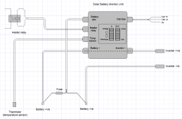
So here's the plan with the battery monitoring, I've come up with a design that will measure the battery current and voltage allowing it to calculate the state of charge then output this together with the Voltage and current limits over Can bus to the inverter.


Solar battery monitor.png


It should make quite a tidy compact and fairly universal unit. It seemed rude not to include a couple of led bargraphs to indicate the charge / discharge current and state of charge just to make better use of the microcontroller, also I've included temperature monitoring mainly so it can control the battery heater via a relay. This then means I can use a really basic BMS, what I don't want to get bogged down with messing about with Bluetooth or trying to program 3rd party components.

Any thoughts welcome:)
 
another 2p worth (I'm keeping a tab ;) )...

So here's the plan with the battery monitoring, I've come up with a design that will measure the battery current and voltage allowing it to calculate the state of charge then output this together with the Voltage and current limits over Can bus to the inverter.
If you're going to use a micro-controller, then why not do as I (and others on the links I shared) have done and read the key data from the (still) basic BMS, via its UART port (def agree not Bluetooth though).

The JBD you are considering will provide you with voltage, current, SOC and temperature anyway, so no need to re-invent the wheel.

I also added some extra temp monitoring, but used DS18B20's (digital) sensors as more accurate and easier to deploy multiple ones to an ESP using one digital input (using the OneWire and Dallas temp libraries).

If, for some reason you do want to measure your own SOC, you may be better off using a Victron Smart shunt, as I understood from other threads on here that is it tricky to get accurate coulomb counting due to noise on the very low voltages you will measure over a shunt. On that note, most shunts connect on the -ve battery side, rather than +ve. Guess that it is because it is easier to measure a small voltage wrt zero, rather than a varying +50Vish amount.
 
I must admit the state of charge is kind of the unknown, I have a good system on my e-bike charger that calculates Ah going into the battery but that's just one way for one charge, any errors over a long period of time would likely end up quite large.

If the BMS can provide SOC then it does make a lot more sense to pull the data from that, it saves a good deal of circuitry, the Hall sensors are horrendously expensive to what I was paying a few years back.

Where are you guys taking power from for the battery heaters? I'm planning on using 8 off 12V / 15W silicone heaters, I can either wire them for 48V and use the battery pack for power or better wire as 24V and run them from an IP67 24V / 10A lighting power supply, I would use a ac transformer but they are a bit scarce and expensive the days.

I think there is a heater output on the BMS but haven't really looked into it yet.

Keep the 2p worth's coming :)
 
Where are you guys taking power from for the battery heaters? I'm planning on using 8 off 12V / 15W silicone heaters, I can either wire them for 48V and use the battery pack for power or better wire as 24V and run them from an IP67 24V / 10A lighting power supply, I would use a ac transformer but they are a bit scarce and expensive the days.
Not sure about the guys one's... but my heaters are 230V powered ;)
 
Thanks SeaGal, your heaters must be quite high power in that case, I was looking at around 7.5W per cell, what do you heat them to? I looked at someone's build and they were heating them to 60 Celsius, I'm hoping he meant 60 Fahrenheit. I'm keen to distribute the heat evenly to all the cells, I had an ebike battery that went badly out of balance once due to some cells heating more than others.
 
Thanks SeaGal, your heaters must be quite high power in that case
Not all all... I have just three 7W heaters, heating the air around the cells. The case has 50mm of PIR insulation. Keeps the LF280K cells around 18-22C when it's sub-zero (had -5C last year) in the garage and they're only on for about 50% of the time.
 
Ah OK, most of the 240V heaters I looked at were much higher power which is why I was looking at 12V heaters. I'm thinking of sticking them to the underside of an aluminium sheet / plate that the batteries will sit on, I'm planning on similar insulation probably 25mm, its good to get some real world temperature figures. Are you using the BMS to control the heaters?

I've just ordered the BMS so I'm hoping to play with it on the bench over Christmas, am I right in thinking that the UART socket uses 3.3V logic? Probably doesn't make any odds as I'm only reading from it.

I'm assuming that the UART connector must be isolated with respect to the battery 0V (possibly an expensive assumption!) ? and this will therefore be happy to be at the same potential as the Can input on the inverter, so all I need to worry about is an isolated 48V to 5V power supply to power the processor and Can interface, in reality 60V to 5V to give a bit of headroom over the charging Voltage.

I'm guessing there is no setting up to do on the BMS, I believe it automatically senses the number off cells and everything else is preset?

I'm installing Visual studio tonight, this is what has been putting me off using the code you pointed me to as up to now all of my programming has been using the Arduino IDE.

I really appreciate your help, its going to help may others who read this as well.
 
Ah OK, most of the 240V heaters I looked at were much higher power which is why I was looking at 12V heaters. I'm thinking of sticking them to the underside of an aluminium sheet / plate that the batteries will sit on
Sounds good - make sure there is insulation between the metal sheet and batteries - as well as insulation between each cell. The blue plastic coatings on prismatics are not safe (insulation-wise) to use on their own.

... Are you using the BMS to control the heaters?
I get 3 temperature readings from the bms (probes are attached to cells at front, back and middle of pack). I also get the temp from a DS18B20 sensor connected to the ESP32. My arduino software then uses min/max values of those 4 sensors to decide that temp to turn on and off the heaters, with those min and max values being configurable via a web interface.

I've just ordered the BMS so I'm hoping to play with it on the bench over Christmas, am I right in thinking that the UART socket uses 3.3V logic? Probably doesn't make any odds as I'm only reading from it.
IIRC the JBD UART operates on 5V levels. I use a voltage divider to drop that to 3.3V to match the ESP32's input pin. The 3.3V output from the ESP32 drives the JBD just fine (I both read and write to the JBD).

I'm assuming that the UART connector must be isolated with respect to the battery 0V (possibly an expensive assumption!) ? and this will therefore be happy to be at the same potential as the Can input on the inverter, so all I need to worry about is an isolated 48V to 5V power supply to power the processor and Can interface, in reality 60V to 5V to give a bit of headroom over the charging Voltage.
Good question and this is an area of investigation I am currently undertaking - my battery system is fully floating, but for some (currently unresolved reason) I've managed to zap a couple of CANBus adapters :( This has only happened when I use the battery disconnector - normally it is running fine with a non-isolated 60V to 5V buck. Please have a read through this thread of mine, which is a work-in-progress...

I'm guessing there is no setting up to do on the BMS, I believe it automatically senses the number off cells and everything else is preset?
LOL.. no... you will need to configure it for everything. Capacity, voltage to SOC settings, over / under protection etc. Here's a link to the setting I was using...

I'm installing Visual studio tonight, this is what has been putting me off using the code you pointed me to as up to now all of my programming has been using the Arduino IDE.
Of course... Simon updated his code to use VS Code... I'm still using Arduino 1.8 :)

I really appreciate your help, its going to help may others who read this as well.
Thanks and 'hopefully' :)
 
Sounds good - make sure there is insulation between the metal sheet and batteries - as well as insulation between each cell. The blue plastic coatings on prismatics are not safe (insulation-wise) to use on their own.
That's a very good point!!! some sort of electrical insulation between the cells might be prudent also.

LOL.. no... you will need to configure it for everything. Capacity, voltage to SOC settings, over / under protection etc. Here's a link to the setting I was using...
That's a bummer, knew it was too good to be true, I guess I'll be needing a Bluetooth adaptor to use my phone or a USB converter to use a laptop (preferred as my phone is rubbish), I think I found the app somewhere on the Overkill site, not sure about the converters though.

Good question and this is an area of investigation I am currently undertaking - my battery system is fully floating, but for some (currently unresolved reason) I've managed to zap a couple of CANBus adapters :( This has only happened when I use the battery disconnector - normally it is running fine with a non-isolated 60V to 5V buck. Please have a read through this thread of mine, which is a work-in-progress...

No worries I'll opto-isolate the TTL uart signals and hold the circuit at the inverter potential, this will also overcome any 3.3 / 5V mismatch issues should they arise. I believe there is a power output for the Bluetooth adaptor, I might be able to use this to power the opto-drivers on the BMS side as I know the signals are very low power and will not drive an led directly.

There are isolated Can bus transceivers out there but they look to use a special transformer for the inbuilt DC/DC converter.

We have possibly similar issues at work with regards to spikes, with high voltage fuel cells we can discharge them completely but the body of the cell can still be floating several hundred Volts above ground so I had to add extra bleed resistors in my discharge kits to bring the hole thing down to ground potential. It's possible something similar is happening if the battery is completely floating so when the switch is closed there might be a Voltage mismatch creating a high current spike that induces into anything nearby, a bit like the nearby lightening strike that took out the RS485 drivers on my weather station.

Are you using a ground with the Can bus? if not that could well produce a too high common mode Voltage between the differential pair and ground that the Can driver can't tolerate.

I know some SMPSU's have a capacitor between the primary and secondary of the transformer to improve EMI performance which is a bit of a frightening thought...
 
Last edited:
some sort of electrical insulation between the cells might be prudent also.
essential.

That's a bummer, knew it was too good to be true, I guess I'll be needing a Bluetooth adaptor to use my phone or a USB converter to use a laptop (preferred as my phone is rubbish), I think I found the app somewhere on the Overkill site, not sure about the converters though.
I have an overkill BMS and got the USB adapter from them - it is badged as a JBD one

... I know the signals are very low power and will not drive an led directly.
Bother.

There are isolated Can bus transceivers out there but they look to use a special transformer for the inbuilt DC/DC converter.
(y)

We have possibly similar issues at work with regards to spikes, with high voltage fuel cells we can discharge them completely but the body of the cell can still be floating several hundred Volts above ground so I had to add extra bleed resistors in my discharge kits to bring the hole thing down to ground potential. It's possible something similar is happening if the battery is completely floating so when the switch is closed there might be a Voltage mismatch creating a high current spike that induces into anything nearby, a bit like the nearby lightening strike that took out the RS485 drivers on my weather station.
Makes sense.

Are you using a ground with the Can bus? if not that could well produce a too high common mode Voltage between the differential pair and ground that the Can driver can't tolerate.
not using ground. Do you mean common mode voltage with or without the ground? I'll see what happens with my tests over the next few weeks - the basic design has been working for nearly 18 months now.
 
My BMS arrived today, only 19 hours after ordering it and 4 days before Christmas! ?

It came with the Bluetooth adaptor already fitted to the UART socket. I hooked it up to an old 10S ebike battery so its alive and communicating with my phone over Bluetooth. There's a couple of small issues like its insisting its connected to 12 cells and not 10, the voltage seems stable but under reading by about 3V and it wont stop beeping but its alive!!

As suspected the UART connecter is at battery ground potential so some isolation is going to be a must.

I think this might possibly point to why your canbus transceivers get zapped, assuming the DC disconnector on the inverter breaks the 0V line to the battery, when the switch is closed the inverter Canbus input will be at the same potential as the battery so all is good but when the switch is opened the battery current is likely trying to return via the Canbus connection until it fails, I think you mentioned somewhere that it blew a fuse in the negative line so it sounds plausible, if you never open the DC disconnector or the BMS never trips it should work fine.
A long time ago I had a car that did something similar, the ground lead to the engine was in poor shape and eventually failed so when I went to start the car the engine earthed itself via the accelerator cable, that was fun, it was an American 6 litre V8 automatic, the throttle then got stuck pulling away, I recall my underpants had to go into soak!!

I've found a likely isolated Canbus chip that should do the trick so I'll get started designing a board, I might use an ESP32 as a lot of people seem to be using those, the board will also have the PSU and RS485 transceivers.

I need to look for a Bluetooth dongle for the PC now so I can get the BMS fully set up, it looks to be quite limited with the phone app.
 
Back
Top