diy solar

diy solar

Experiences charging LFP from alternator WITHOUT a DC-DC charger

I have been regularly maxing out the 200A bosch internal fan alternator on my van for 5+ years (100k+ miles). Charging/running my induction cooktop at idle (100-120A hot idle). This also included charging my 500AH+ lead acid bank, and now my 560AH lithium bank. At fully loaded hot idle (100-120a), the alternators case stays under 220F.
I keep staring at this alternator charging issue and can't seem to get myself to give in and just order a DC-DC charger (or few). I likely still have a few weeks until my batteries are here, but I can't shake the feeling none of that is necessary for a battery bank at the same voltage as the alternator and it's suboptimal.

Your adding credence to my theory, only I have no way of knowing that my alternator is as well built as yours (2007 ford so likely not). Here's my plan: Figure out a way to probe the temperature of my alternator and hook up my batteries through a large 500a relay (stock 150a alternator, but I don't trust the ratings on those things and it's only $50). I then let the truck idle (worst case for alternator right?) and fire the relay so my mostly discharged ~540Ah LiFePo4 batteries are connected and observe the current draw, voltages, and the temperature of the alternator. If it can handle it yay, I just need to add some logic to disconnect when the battery is full (talking to the 2 overkill BMS units on an arduino - I'm a firmware engineer ?).

If it looks like the alternator can't handle it (it's getting increasingly too hot) I'll add an appropriate resistor to reduce the current to what it can steady state in that worst case and add another relay with no resistor connection. I'll then program up some logic on when to engage the full current and when to drop to the reduced current along with the total disconnect when full logic.

Alternately if I can get the temperature probe reading to the arduino and it seems solid I can make that decision based on how the alternator is actually doing. But with the temp reading I may just stick with one relay (with no added resistance) and simply disconnect when it gets too hot for a while (I think the presence of the starter battery makes that ok).

Of course I can't really test worse case summer conditions at the moment, but I just don't like the DC-DC solution and I wouldn't mind upgrading my alternator anyways if I get it wrong and end up burning the thing up.
 
Last edited:
I keep staring at this alternator charging issue and can't seem to get myself to give in and just order a DC-DC charger (or few). I likely still have a few weeks until my batteries are here, but I can't shake the feeling none of that is necessary for a battery bank at the same voltage as the alternator and it's suboptimal.

Your adding credence to my theory, only I have no way of knowing that my alternator is as well built as yours (2007 ford so likely not). Here's my plan: Figure out a way to probe the temperature of my alternator and hook up my batteries through a large 500a relay (stock 150a alternator, but I don't trust the ratings on those things and it's only $50). I then let the truck idle (worst case for alternator right?) and fire the relay so my mostly discharged ~540Ah LiFePo4 batteries are connected and observe the current draw, voltages, and the temperature of the alternator. If it can handle it yay, I just need to add some logic to disconnect when the battery is full (talking to the 2 overkill BMS units on an arduino - I'm a firmware engineer ?).

If it looks like the alternator can't handle it (it's getting increasingly too hot) I'll add an appropriate resistor to reduce the current to what it can steady state in that worst case and add another relay with no resistor connection. I'll then program up some logic on when to engage the full current and when to drop to the reduced current along with the total disconnect when full logic.

Alternately if I can get the temperature probe reading to the arduino and it seems solid I can make that decision based on how the alternator is actually doing. But with the temp reading I may just stick with one relay (with no added resistance) and simply disconnect when it gets too hot for a while (I think the presence of the starter battery makes that ok).

Of course I can't really test worse case summer conditions at the moment, but I just don't like the DC-DC solution and I wouldn't mind upgrading my alternator anyways if I get it wrong and end up burning the thing up.
There are other considerations other than if your alternator can handle it, or if you need to reduce the output. If the BMS disconnects, not only will it damage the alternator, but it can blow out nearly all other electronics in the vehicle. The DC-DC charger deals with that issue as well.

The following is in my opinion a must read. It is geared towards boats, but applies to any vehicle. This is written by a true expert, who has installed hundreds of systems, and also repaired systems that were done wrong and damaged. It's long and all a good reading, but relevant to this thread you can search to the bottom for "Alternator Considerations for LiFePO4"

 
If the BMS disconnects, not only will it damage the alternator, but it can blow out nearly all other electronics in the vehicle
Simply not true as I discussed above. Only specific setups have this issue. I have examined voltage transients for a number of alternator setups which still have a primary battery for buffer. The voltage spikes even when disconnecting a 150 amp load, do not result in transients exceeding approximately 16 V for a 12V system. It may seem like a lot, but that is well within the design tolerance for automotive electronics.

As mentioned marine systems are not readily applicable to anything made in the last 20 years in the automotive market. Look at some of the alternators they are using the designs are truly dinosaur, no digital feedback no thermal specific scaling, and extremely low inertia. Comparing them to modern automotive alternators is akin to talking about lugging with regards to carburetors, coldstart warm-ups etc for engines made in the 60s and 70s.

They are also much less risk tolerant due to Deepwater sailing concerns. There aren't any auto parts stores in the deep blue.

An 07 Ford is probably modern enough to have a reliable alternator.
 
Last edited:
So far only 4 months on a 220 amp alternator -> 240Ah lifepo4 house battery. This has been winter so batteries have been in the 5-15C range. Resistance between vehicle battery and lifepo4 is 9mR. the peak charge rate I have seen is 160A at a 25ish percent state of charge (at idle!). Usually it sits around 80-100 amps before dropping off near the end of charge. For summer I have added a 10mR resistor to the circuit to limit the charge rate to 60-70 amps. I am very curious to see how this works out long term.

I do not float the batteries. At either 3.6 volts on a cell or the charge rate dropping below C/10 (both alarmed) I disconnect manually.
 
Simply not true as I discussed above. Only specific setups have this issue. I have examined voltage transients for a number of alternator setups which still have a primary battery for buffer. The voltage spikes even when disconnecting a 150 amp load, do not result in transients exceeding approximately 16 V for a 12V system. It may seem like a lot, but that is well within the design tolerance for automotive electronics.

As mentioned marine systems are not readily applicable to anything made in the last 20 years in the automotive market. Look at some of the alternators they are using the designs are truly dinosaur, no digital feedback no thermal specific scaling, and extremely low inertia. Comparing them to modern automotive alternators is akin to talking about lugging with regards to carburetors, coldstart warm-ups etc for engines made in the 60s and 70s.

They are also much less risk tolerant due to Deepwater sailing concerns. There aren't any auto parts stores in the deep blue.

An 07 Ford is probably modern enough to have a reliable alternator.
I agree if you have a FLA battery as a buffer, that solves the problem. So will a Sterling protection device. I missed the post where it was discussed that those were part of the installation. Point being, you can't just connect an automobile alternator to a Lifepo4 bank.

I 100% disagree about your perceived quality of marine alternators. Yes, the alternators engine manufactures supply are junk. They are simply repurposed auto alternators-not marine alternators. Any boater that really uses their boat scraps that alternator for a high quality alternator, with external regulation, temp sensors on both the alternator and (if they still use lead batteries) temp sensors on the battery. Fully programmable charging stages and voltages, and at what temps and how much to derate for over temp. For many years it's been common to have 1000Ah AGM bank on a boat. The crappy stock alternators will struggle with that just as they will with Lifepo4. When anyone says marine alternator, they are talking about a quality aftermarket alternator, not the repurposed auto alternator that engine manufactures give you for free.


If you have not taken the time to read the article, I suggest you do. It reflects thousands of hours of testing for over 15 years, and hundreds of lithium installs, by an engineer that repairs and custom builds alternators. Far more credible than anecdotal evidence from a couple people that have had some success.
 
If you have not taken the time to read the article
I have followed the author for years, and it's good info. But my points about alternator design hold. The information is simply not directly applicable to modern alternators operating in an automotive environment. 65-90A fully analog alternators designed in the 70s or 80s for light-duty automotive applications when cars didn't have air conditioning or high-powered electronics, then stuck onto diesel engines in a marine environment operating in a closed engine compartment often at lower than spec speed. These alternators will of course fail with regularity if loaded anywhere near their rated power.

The author is specifically talking about marine applications, with hot compartments. How many vehicle Alternators have you seen blown up by high current loads? I worked a fair bit with an ambulance builder and maintainer, and they routinely slammed their alternators for 100-200 A at idle for thousands of hours a year. The reliability was quite good even with factory alternator packages.

That being said I'm sure there are a small number of automotive applications where the alternators cannot be pushed to supply 80-100% of the rated power continuously. However these are in the minority . I still agree that is incumbent on the person doing the install to do the research or testing themselves. This is typically fairly straightforward, apply a load to the alternator at idle until you reach its maximum current potential. Measure the case temperature of the alternator with a contact thermometer or quality infrared thermometer. If it stays under 220° plus any ambient temperature variations then it is probably good to go.
 
Last edited:
I have followed the author for years, and it's good info. But my points about alternator design hold. The information is simply not directly applicable to modern alternators operating in an automotive environment. 65-90A fully analog alternators designed in the 70s or 80s for light-duty automotive applications when cars didn't have air conditioning or high-powered electronics, then stuck onto diesel engines in a marine environment operating in a closed engine compartment often at lower than spec speed. These alternators will of course fail with regularity if loaded anywhere near their rated power.

The author is specifically talking about marine applications, with hot compartments. How many vehicle Alternators have you seen blown up by high current loads? I worked a fair bit with an ambulance builder and maintainer, and they routinely slammed their alternators for 100-200 A at idle for thousands of hours a year. The reliability was quite good even with factory alternator packages.

That being said I'm sure there are a small number of automotive applications where the alternators cannot be pushed to supply 80-100% of the rated power continuously. However these are in the minority . I still agree that is incumbent on the person doing the install to do the research or testing themselves. This is typically fairly straightforward, apply a load to the alternator at idle until you reach its maximum current potential. Measure the case temperature of the alternator with a contact thermometer or quality infrared thermometer. If it stays under 220° plus any ambient temperature variations then it is probably good to go.
Look at the Nordhavns with their diesel hybrid drives, new boats have some sophisticated electronics and alternators.
Most new alternators deal with high draw and sudden stops etc. Only thing I worry about is the max amp out vs ALT rpm.

--
The guy in the video and his solution - I will not do it, when I am out at sea for days/months I want a predictable system. Adding a current limiting charging solution is "cheap".

After one pays for a sea tow once, you learn very quickly the meaning of "gangsta swag $$$" and what it is like not to have it. :rolleyes::rolleyes:
 
Thank you for sharing,
Can anyone comment why it would go from 160A down to 80A? the chart I have seen about internal resistance versus SOC shows that resistance decreases with charge.
Is the alternator regulator lowering the current because it is getting warm?
thank you
As the voltage on the cells rises the difference between the alternator voltage and cell voltage drops. This leads to the drop in charging current. I used some cell voltage vs. state-of-charge vs. charge rate data to estimate the current trend and it matched quite well. Of course, I dumped the data into a spreadsheet and cannot find the original paper anymore!

I believe that during charging the internal resistance of the cells is not the main driver of the charge rate (although it is clearly important!). In these cells the internal resistance is only a fraction of the resistance in the wiring+connections+shunt+fuse. The real limiting factor is the limited voltage difference between the 14.4V at the alternator minus the voltage drop through the wiring and the lifepo4 voltage. At high charge rates the lifepo4 voltage is also significantly higher than the resting voltage due to diffusion limits in the cells.

Time will tell if a simple resistor is an ideal current limiter. I hope to collect data on a full charge cycle in the next few days.
 
Last edited:
potential difference, imagine, 2 water tank connected at the bottom, one empty and one full,

Once you open the valve water flow from one tank to the other till they both have the same height (volts)
 
Alternators are inherently current limited by their design.

As far as limiting charge current to less than the alternators output minus additional loads, it is possible to use wire resistance to do this though not always practical.
 
Thank you bzzt. Do you mind to share the size of your battery LFP bank? 280ah? do you know if your alternator is temp regulated? I've read that almost all of them are; so it could be the alternator limiting the current on high temp. I just found one alternator from Leece-Neville that is: "High Temperature rated to 125oC with No throttle-back regulator, maintains output at high temperatures" and continous duty at 12,000rpm (alt rpm). Trying to figure out what the limit on current is cause if it is not going to charge more than 80A most of the time no need to though more money at it lol. Thank you!
The battery is a 240Ah unit made up of 120Ah cell pairs (2p4s)? I wanted some redundancy! I suspect the alternator has protection BUT the voltage at the van battery has been more or less constant during charging, so the alternator has not entered any protection mode.

The one time I saw 160 amps was after drawing the lifepo4 down to 12 volts. This is lower than I normally go! The voltage at the cells rose quite rapidly and the current dropped to the 80-100 amp range for the duration of the charge.

I recently added the 10mR resistor to the system just because I don't need to charge so quickly and with summer coming up I thought it would be nicer to the alternator. That said, I can easily bypass the resistor for higher charge rates (or if it's -30 and I am not worried about the alternator overheating!).

It is hard to find hard numbers out there to support or debunk direct charging! I went with the direct connection based on a single bit of 'internet evidence' suggesting that below 300Ah you probably don't need to throttle. Unfortunately I failed to collect data with the base setup (bad coding). I will post the charge rate data that I collect with the resistor (~20mR TOTAL resistance) since this question keeps coming up.
 
I just read in some other forum that the alternator regulator also wont put the alternator voltage up unless there is enough headroom between the amps pull out and the max amp of alternator.
Then I also read a Ford owner who has the Leece_Neville no temp throttle alternator and has proved/tested that it does throttle on temp.
There seems to be so much confusing info out there.....then there's people building dc generators with a junk 7hp motor and junk alternator pulling 200a or more. It would be nice to put in 400A in an hour of driving instead of 4 on a truck that already has 250HP lol.
Yep, the power required to charge the batteries is trivial compared to a cars engine! In my case, putting away almost 200Ah in a couple hours of driving is great and one of the main reasons I upgraded to lithium in the first place! A 40 amp DC-DC charger would almost be a downgrade to my old lead-acid charge rate.
 
Alternator regulators (with a few rare exceptions) have no way to measure output current directly.

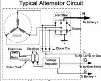
The regulator supplies up to battery voltage to the field coil. The number of windings, gauge, and rectifier design determine output current. For example many alternators use the same regulator for both 100 and 200A units.

The regulator simply tries to attain its voltage target. This target can change with alternator temp, or with time (some start high and taper down a bit. It does this by changing how much voltage is applied to the field coil. More voltage on the field coil (up to the battery voltage) will be applied. Once that max field voltage is attained, the alternators current cannot rise any further. This self regulator behavior is the reason that a starter/primary battery must always be connected to the system. Otherwise a sudden load shed would cause a positive feedback loop, where the voltage could spike to 2-5x normal. The starter battery suppresses these spikes.

If a demand greater than the alternators output is applied, such as a big battery or similar, the system will find an equilibrium at less than the alternators target voltage. For example a big discharged LFP pack may pull an alternator down to 12.5V for the initial part of the charging. As the battery SOC rises so will the alternator voltage. Once the system equilibrium drops below the alternators current limit, the voltage will then rise to the alternators setpoint.

Wiring resistance and alternator temperature will affect charge rates, as will battery SOC. These all work to produce an equilibrium in both voltage and current. The high end of voltage being limited by the alternators regulator setpoint, and the high current limit being a function of the alternators design.

My 500AH 12V bank will take all my alternator has to spare right until about 95% SOC. This is about 100A at idle, and 150A at 2k rpm. This is a 200A unit, and it will make about 180-190A hot and at high idle. Engine and vehicle systems consume some of that, so I have 100-150A available for charging.

Now "smart" alternators often have a digital bus connection to the vehicles ECU/modules. These systems can vary the voltage to save energy. Some actually have a crude current measuring shunt on the battery. This lets the ECU drop the alternator voltage (with a command to the regulator) once the starter battery is full.

For these systems you can often connect directly to the starter battery for the aux battery. The ECU will see the charging load and keep the alternator voltage elevated. Otherwise voltages below the charging range for LFP may happen.

For these dynamically variable alternator systems where the low voltage situation cannot be remedied, a DC-DC is the only option for charging.
 
To expand a bit further, most alternator designs are something like this (some models have internal excitation, and most don't need a ignition voltage supply). Some may have more phases, or different configuration stator windings. Older models use a totally analog regulator. Newer models still use analog for high speed voltage response, but its monitored by a digital chip. This supplies the voltage reference signal, reacts to temperature and voltage spikes (some alternators will lock out after a excessive spike), and can do voltage/time curves in some cases.

1616282790971.png

External regulators can be added, or in some cases retrofitted. These allow limiting charge current, using external signals, or voltage profile adjustment. Not common in the automotive world, and not easily retrofitted to most modern alternators not specifically designed for them.
 
Time will tell if a simple resistor is an ideal current limiter.
Ideal is only limiting the current as needed to keep from killing the alternator - which is done automatically for many of us it sounds like (we still need to disconnect when battery full is needed to protect the battery). The issue with just adding a resistor like that is your reducing current at all times to the needs of your worst case. On the other hand if that reduced rate meets your requirements there's nothing wrong with the extra piece of mind that gives.

After hearing from Luthj (who obviously has a bit of experience and knowledge here) I'm of mind to give it a go. If the alternator fails I have a rather large battery and solar to lean on. I wouldn't mind an alternator upgrade anyways.
 
The disconnect issue really depends on duration and voltage. If your alternator is at say, 3.5Vpc, and you will only see the pack at the voltage for 100Hr a year, then it really isn't a big deal. Current tapers to nearly zero at that point, and the whole overcharge thing doesn't occur. There is some capacity reduction from sitting at high SOC and voltages, but its cumulative, and take a fair amount of time.
 
The disconnect issue really depends on duration and voltage. If your alternator is at say, 3.5Vpc, and you will only see the pack at the voltage for 100Hr a year, then it really isn't a big deal. Current tapers to nearly zero at that point, and the whole overcharge thing doesn't occur. There is some capacity reduction from sitting at high SOC and voltages, but its cumulative, and take a fair amount of time.
Especially with a direct connection I foresee many hours driving with completely full batteries. It could be a manual disconnect I suppose, but I think it nessessary.
 
Especially with a direct connection I foresee many hours driving with completely full batteries. It could be a manual disconnect I suppose, but I think it nessessary.
I have followed Rod Collins' (Marine How To) advice on lifepo4 charging. He strongly asserts that with these cells the charger must STOP after achieving full charge. Unlike lead acid you aren't just boiling off water if you continue. You are permanently damaging the battery if you continue to charge past 100%, even at voltages well below the typical high cutoff we use. In my case, I disconnect at either 3.65 volts or once the current drops below 24 amps. This isn't based on any of my own experience, just Rod's assertions, which are definitely worth a read. https://marinehowto.com/lifepo4-batteries-on-boats/
 
Ideal is only limiting the current as needed to keep from killing the alternator - which is done automatically for many of us it sounds like (we still need to disconnect when battery full is needed to protect the battery). The issue with just adding a resistor like that is your reducing current at all times to the needs of your worst case. On the other hand if that reduced rate meets your requirements there's nothing wrong with the extra piece of mind that gives.

After hearing from Luthj (who obviously has a bit of experience and knowledge here) I'm of mind to give it a go. If the alternator fails I have a rather large battery and solar to lean on. I wouldn't mind an alternator upgrade anyways.
I totally agree. I think of the resistor as ideal in the sense that if you want to limit current it is simple, cheap, and (with the flat voltage profile of lifepo4) should provide a fairly constant current to the batteries.

So far I haven't had any issues with my straight 'non-throttled' connection though! I suspect my alternator is smarter than me.
 
There is a high chance that a failing alternator in a modern vehicle will take some/all of the vehicle computer modules with it.
So far I haven't had any issues with my straight 'non-throttled' connection
Do the sums and calculate the resistance of the path between the alternator and the battery, factor in the battery internal resistance and the alternator output resistance. This is limiting the current together with the alternator volts drop as it approaches full power output.

Mike
 
Back
Top