diy solar

diy solar

Fortress eFlex and eVault Max owners can now use Solar Assistant and Closed Loop Together on Sol-Ark.

robby

Photon Vampire
Joined
May 1, 2021
Messages
4,129
For the owners of Fortress eFlex and eVault batteries like me it has always been a tough choice if you want to use Solar Assistant on a Sol-Ark Inverter.
You either give up the ModBus 485 port for Solar Assistant and lose closed loop communication with your batteries or you Plug out the WiFi Dongle and lose the use of Powerview. I chose keep Powerview and to give up closed loop communication.
It has nor been a good experience using Voltage mode as the SOC can be wildly off, but I really wanted realtime data from Solar Assistant.

The good news is that a solution has been created. The newest eFlex/eFlex max Firmware from Fortress can now use the Canbus Port to talk to Sol-Ark Inverters and therefore allow Sol-Ark owners to use an Ethernet Y adapter to plug in both the Batteries and the Pi for SA at the same time using lithium mode 0.

I am happy to say I updated all of my eFlex batteries several days ago without any issues and everything is working great. I now have true SOC readings as well as SOH of the battery and it still sets voltages and controls the charge current of the Sol-Ark.

The only negative I have seen so far is that it no longer automatically knows how much is the total current of all the Packs I have hooked up.
I suspect that they have hit into some of the limitations of using Lithium Mode 0. So now have to set it manually and lose some of the added automatic protection.

In any case this is a huge upgrade for me as I have been using Batt-V mode and suffering with SOC numbers that are off by as much as 30%.

The software is now available for the Public download at Fortress.

https://www.fortresspower.com/firmware/

Please note this update requires that you have the Canbus Interface tool, a PC laptop with Win 7 or 10.
Also you need to Install the drivers and run the KR100 program from the folder. You also need to make a new cable between the last battery in the chain and the Sol-Ark Inverter. It is now using Pins 4,5 and 6 instead of 7&8.
There are Instructions included in the Link but keep in mind that once connected to the Battery (eFlex Only) you need to determine if your BMS is a Revision A or B model. Only the most recent batteries sold are Rev B. Once you get the software running and connected you need to look at the firmware version of your battery.
If it say 27xx then it is a REV-A battery. If it says 40xx then it is a REV B. So download the Firmware update that is for your Version.
You must use the latest Drivers and BMS software. Also please note there is a section in the instructions that tells you to Set the Canbus number to 2.
It will not work without each battery being set correctly after the update. Each battery must be done one at a time and not be data connected to the others and it must also have it's negative lead disconnected.


I don't know what is happening with the eVault Classic but I would imagine that they are going to be making a similar firmware version very soon.
 
Last edited:
Hi @robby I will be starting a Sol-Ark 15K/eFlex install soon, and I am interested in this setup. How is everything working?

Does anyone have this, or SA in general, setup with a 15K, and is it fully supported?

Can you explain this part a little more?

The only negative I have seen so far is that it no longer automatically knows how much is the total current of all the Packs I have hooked up.
I suspect that they have hit into some of the limitations of using Lithium Mode 0. So now have to set it manually and lose some of the added automatic protection.

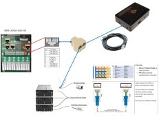
I made this sketch to make sure I understand, is this how you have it cabled up?


SolArk-SA.jpg

Here is the eFlex documentation I found for this

Here is the SA documentation (Under Sol-Ark 12K Outdoor)

The only thing I haven't found is any documentation for this setup on the Sol-Ark side, so I may send them a question asking about it.

Thanks

Craig
 
Hi Craig
It's been working great :):)
Your drawing is correct, you just need to make one cable to the eFlex that uses Pins 4,5,6 and then make another one that goes to your Pi USB adapter that uses pins 7 and 8.
Try each device separately in the port and make sure they work. After that then combine them using the Y adapter.
All the other eFlex batteries are chained together using regular Ethernet cables, it's only the last one in the chain going to the Inverter that needs to be wired to the Canbus pins only.
Thanks. And you still use the 'pinout converter', I guess that comes with the eFlex?

What SA USB cable are you using? Did you buy the one from SA/Watts247, or something else?
 
CM119, Please continue to use the pinout converter - it terminates the communication circuit between eFlex with an in-line resistor while passing ALL pins through the pinout converter. Without doing any real "conversion". Its an awkward name.

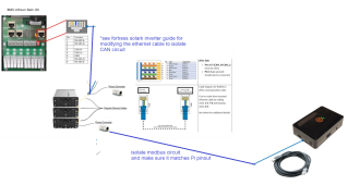
You might find this wiring arrangement to be more convenient if you have multiple pinout converters left over in the packaging.
If you want another pinout converter and fill out a fortress technical support ticket, they will mail you one.
1673995760179.png
 
Last edited:
@jrcromer thanks. In more research after this post I found a better description of that 'pinout converter' and what exactly it's used for in one of the Fortress videos. I agree it could use a better name.

As for your new diagram, that does look like a good solution, however I ALSO just ran across the Fortress Guardian, and now I'm considering installing that as well for better battery visibility. Will the Guardian integrate well with this setup? So the CAN bus would then have Sol-Ark, Solar Assistant, eFlex batteries, and Guardian all on it. Since the Guardian looks to install on one end of the string, I would still need a splitter cable somewhere it appears? Or does the Guardian have any kind of 'pass through' function?
 
The guardian still needs some time to bake to get any advanced monitoring out of it. The first production batch is just getting the market and there's a lot of software development that is yet to come.

I think you will have a better experience getting solar assistant to work and just utilizing solark monitoring system. If you fill out a support ticket with your eflex serial number, tech support will send you one of our firmware update tools (which the guardian will eventually replace). The firmware update tool is needed to convert over to solark canbus communication and requires a windows laptop - again the support ticket process of in the fortress website is your friend here.

While the firmware update tool is clunky, if you are a tinkerer the process can be somewhat fun as it lets you see a little but more "under the hood" than what more consumer friendly monitoring hubs will allow. Useful to have in a drawer for a rainy day if you have a good enough excuse to get one for free from tech support (right now we are mailing them to customers who want to switch from modbus communication over to solark canbus communication, a necessary step to run solar assistant until the next batch of eFlex hits distribution). A very recent change as we have been running of solark modbus for a couple years. We've found canbus to be much more stable and precise when communicating with solark's especially the 15ks.
 
Sol-Ark just released a new Battery guide interface manual.
Of note is this line:

As of Jan 19, 2023, Sol-Ark recommends CAN bus battery mode where feasible or else Modbus RS485 or else
ungrounded RS485. OR if you only have a cable for Modbus RS485: use prior inverter MCU firmware version
[6212 outdoor for 12k inverter, or 7212 for 15k inverter] with Comm v1432 and latest follower MCU version.
The image below depicts the screen shown under “Settings > LI Batt Info” when communications are enabled
for Modbus/RS-
485 batteries (All other “BMS Lithium Batt” modes)

This lines up with some comments I heard that a move to Canbus eliminates some sort of issue the 15K has with RS485 and using the latest firmware.
 
Correct. We've seen modbus to be unreliable enough, mostly with the 15k. Not as involved on the front line to speak intelligently as how broadly applicable this is to the 12k, or smaller models. My advise is that to switch if you have the 15k but if your 12k, 8k, or 5k is working fine, then just let it be. Fortress customers wanting to migrate to CANbus communication to Sol-ark can get a new communication cable and firmware update tool, as well as technical support assistance, through our support portal.
 
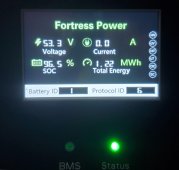
After updating the Fortress eVault Max firmware and making your new cable, be sure to switch the protocol ID on the eVaults to 6. It took me the better part of an hour to finally figure out what broke.
 

Attachments

  • 20230203_142353.jpg
    20230203_142353.jpg
    225.6 KB · Views: 5
@robby / @jrcromer : Hi guys -- great to hear these updates on Fortress Power. I am excited to start getting SA working so I can view/control my solar data more robustly.

I had my solar installer upgrade the battery firmwares and confirm we are using CanBUS to talk between the SolArk 12k outdoor and the fortress power batteries I have (4 x 5.4kWh eflex). I cannot, however, get SolarAssistant to see any data coming out of the inverter.

I am using one of the USB cables that SA sells and a ethernet splitter as SA recommends. If I just plug the SA usb-wire directly into the CanBUS port (eliminate splitter) it still doesn't see any data. In SA, it can definitely see the serial adapter in the cable in the kernel messages concerning USB devices. I also tried using screen and minicom on that serial tty, and I never see any data coming through it.

which leads me to a question -- do you have to fully power down the inverter to get it talking RS485 under BMS lithium battery 00 setting?

Or, I also saw mention of setting some canbus setting in the batteries to "2", although I am not sure what effect that would have? The PV Pro webapp is seeing the battery SoC from CanBus now. What failure would not setting (whatever setting this is) this to 2 cause? Is this the "UPS-CAN: setting mentioned on pg 31 of these instructions (https://www.fortresspower.com/wp-co...lex-Firmware-Update-Instructions-5.18.23.pdf)

Does anyone have any other ideas I can try? Thanks in advance :)
 
I plug the batteries into the Inverters Canbus port on the Sol-Ark and then use the RS485 port on the Sol-Ark to connect to Solar Assistant.
SA gets the battery data from the Inverter.
It requires a RJ45 Y splitter so that the one port can connect to two devices. The Sol-Arks battery port is both RS485 and Canbus, it just depends on the pins you connect to.
 
Last edited:
@robby: rereading this:
"I plug the batteries into the Inverters Canbus port on the Sol-Ark and then use the RS485 port on the Sol-Ark to connect to Solar Assistant.
SA gets the battery data from the Inverter.
It requires a RJ45 Y splitter so that the one port can connect to two devices. The Sol-Arks battery port is both RS485 and Canbus, it just depends on the pins you connect to."

The first sentence makes it sound like you are not using an RJ45 splitter -- it sounds like you are plugging the batteries into CanBus port and the SA cable into the modbus/rs-485 port.

Then the second sentence says you need the splitter going into the one port (this is what is in the diagrams above on this thread). I am being dense, I think, and am confused by those statements. Can you please clarify?

Also, what wire are you using to connect the SA to the inverter (or RJ45 spllitter)? I know you mentioned this in a different post somewhere on this forum, but I cannot locate it right now. I am using the cable recommended from SA. I have noticed that it uses pins 1/2 instead of 7/8. Reading the integration guides, it seems like this should work, but it doesn't work even being solely plugged directly into the CanBus port.

Any help you can provide here would be appreciated :)
 
@robby: rereading this:


The first sentence makes it sound like you are not using an RJ45 splitter -- it sounds like you are plugging the batteries into CanBus port and the SA cable into the modbus/rs-485 port.

Then the second sentence says you need the splitter going into the one port (this is what is in the diagrams above on this thread). I am being dense, I think, and am confused by those statements. Can you please clarify?

Also, what wire are you using to connect the SA to the inverter (or RJ45 spllitter)? I know you mentioned this in a different post somewhere on this forum, but I cannot locate it right now. I am using the cable recommended from SA. I have noticed that it uses pins 1/2 instead of 7/8. Reading the integration guides, it seems like this should work, but it doesn't work even being solely plugged directly into the CanBus port.

Any help you can provide here would be appreciated :)
correction: the SA cable doesn't work when solely plugged into the CanBUS port with BMS li Batt Mode set to 00. Back when it was set to 04, I believe plugging the SA cable solely into the CanBus port worked.
 
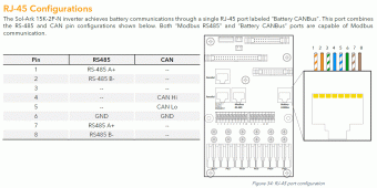
See attached. The port labeled "Battery CANBus" has both CAN & RS-485 communications. A splitter like this
allows a battery to communicate via CAN on pins 4-5-6 and SA to read RS-485 on 1-2 (or 7-8) & 6.

The splitter just allows two different cables/items to interface with the single connector.
 

Attachments

  • 15K Comms.gif
    15K Comms.gif
    110.9 KB · Views: 11
Thanks for the replies @robby and @2TrevorJ !

Yes -- this is exactly what I have -- a small cat6 jumper going to an RJ45 splitter with one leg of the splitter being the SA cable (pins1/2, it looks like) and the other being a standard ethernet cable with 1-3 and 7/8 twisted pairs cut mid run (for the CANBUS connection to the batteries).

It is strange -- I feel like, when the BMS Li Batt setting was 04 the SA would work when solely plugged into the CanBus port. Now that the setting is 00 for CanBus comms, it doesn't.
Did you update the eFlex firmware? Only the newer versions support the Canbus connection on the Sol-Ark.
 
Back
Top