diy solar

diy solar

GFCI outlet with N/G bonded(just kidding) MPP Solar all-in-one inverter on battery power questions.

BobShrunkle

New Member
Joined
May 1, 2024
Messages
22
Location
Utah
So I have my system up and running in my camper and I'm wondering if I can get the GFCI outlet to work with how my setup is configured.

My all-in-one inverter is the MPP PIP1012LV-MS.

The GFCI measures 120v hot to neutral, 120v hot to ground and 0v neutral to ground. Circuit tester shows correct wiring at GFCI outlet.

So based on those 4 measurements I'm WAS assuming the inverter is bonded when off grid.

However the GFCI does not trip when tested from itself or from my circuit tester.

What am I missing?
 
Last edited:
Do you have any grounding setup on the AC side ?
I'm not sure how the GFCI test button works, but if using a proper tester on the socket, it basically bleeds a small current between hot and ground/earth, enough to trip the gfci. But, if you do not have a real ground, I would think that there is no place for the current to go to, hence it's not tripping.
 
Your numbers and assumptions seem to be good. It should trip. Does the GFCI trip when on pass through power? Seems like a bum GFCI to me.
 
This would imply that the GFCI is bad. A GFCI is just a CT wrapped around hot and neutral that trips the circuit whenever it senses positive current flow, so it is not really affected by wiring errors.

However, I have recently noticed I have a GFCI/AFCI that nuisance trips on inverter power but not grid power, and I am still looking into that, so I'm more accepting that there can be strange interactions now.
 
Do you have any grounding setup on the AC side ?
I'm not sure how the GFCI test button works, but if using a proper tester on the socket, it basically bleeds a small current between hot and ground/earth, enough to trip the gfci. But, if you do not have a real ground, I would think that there is no place for the current to go to, hence it's not tripping.
For grounding on the DC side the Battery neg is attached to chassis.
On the AC input side from shore power the breaker box is grounded to chassis.
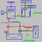
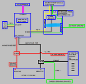
The breaker box has one breaker and only feeds the inverter when on shore power.WIRING DIAGRAM WITH BUS BAR.png
 
Do you have any grounding setup on the AC side ?
I'm not sure how the GFCI test button works, but if using a proper tester on the socket, it basically bleeds a small current between hot and ground/earth, enough to trip the gfci. But, if you do not have a real ground, I would think that there is no place for the current to go to, hence it's not tripping.
I had a similar problem on an off grid system. I simply plugged in a simple outlet tester (10$ or so at the big box stores) and it 'bleeds' enough to allow things to work as expected with a non grid bonded system. YMMV. My electrician did the 'huh' when I told him it worked...
 
I initially set up the inverter to never charge on grid power just while I was getting things going.
Maybe if I go back in and change that setting to solar first and grid second it will pick up the AC chassis ground.
 
If a GFCI is powered up, the test button on it should work whether the ground is bonded or not.
 
This is getting stranger. I just did another test with two outlet circuit testers to make sure one wasn't bad.
First off... the test button on the GFCI does trip it.

When I plug in both of my testers one at a time they both show correct circuit, but when I push their test button neither one will trip the GFCI.
When I push the test button on both testers they show reversed polarity.
When I plug both in together one stays on correct wiring but the other changes to open ground. :fp2
 
Last edited:
I'm voting for open ground. Your GFCI has power, it's TEST button confirms power and leakage tripping. You don't need the ground wire for self test. Your plug in tester probably have a 20Kohm resistor and push button between the hot and ground pins. When you push the button, 6mA of current flows to the ground and that will cause a hot-neutral imbalance and trip the GFCI. This only works when the ground is bonded to the neutral on the line side.

I looked in the manual and program setting #38 speaks of an external grounding box to make the neutral-ground bond. My current working theory is that you don't have a bond but rather some high resistance connection between the neutral and ground. Using a high impedance meter, it will read 120V but if you put an old fashioned 100W light bulb between the hot and ground, it won't light. I think that the high ohm bond is fooling your 3 light testers as well. Plugging both in, begins to make the bond via the lights of the testers.

Try a hard bond on the line side.
 
A Clue!

I just put the inverter in bypass mode and plugged in shore power. The GFCI trips when pushing its test button, it trips when I use a circuit tester test button, and I don't get any weird reversed polarity lights. It also tripped the supplying grid GFCI outlet.
So I'm assuming the neutral ground bond from my shore power(my house) is functioning correctly in the inverter.
Now I need to figure the bonding when I'm on battery power.
Something is not adding up here.
On your original post you stated that there is continuity between neutral and ground when the inverter is on battery.
So in effect, it should act the same when running on battery as in AC IN. It probably has an internal relay (as some but not all off-grid inverters have) that connects N-G together when not connected to grid.

Are you sure you have grounding properly setup when not connected to grid? If so, how did you accomplish this?

So I think you are fine in regards to N-G bonding (you don't need to do anything else), but you have an open ground. As you are in a camper, I suppose to need to run a ground rod somewhere. Probably not easy when on the go.
 
A Clue!

I just put the inverter in bypass mode and plugged in shore power. The GFCI trips when pushing its test button, it trips when I use a circuit tester test button, and I don't get any weird reversed polarity lights. It also tripped the supplying grid GFCI outlet.
So I'm assuming the neutral ground bond from my shore power(my house) is functioning correctly in the inverter.
Now I need to figure the bonding when I'm on battery power.
You proved my theory correct. Now the hard part, finding the external grounding box that is noted in the instruction manual. Your inverter will pass the shore power neutral-ground bond through but when on battery (inverted) power there is no bond. The program setting #38 controls the dry contact of the inverter. That dry contact would energize a relay to make the neutral-ground bond. It's a simple circuit, but I don't know where to find one.
 
Are you sure you have grounding properly setup when not connected to grid? If so, how did you accomplish this?
For grounding on the DC side the Battery neg is attached to chassis at a single location.
On the AC input side from shore or grid power the breaker box is grounded to chassis at a single location.
The breaker box has one breaker and only feeds the inverter when on shore power.
My diagram above is pretty simple.
 
You proved my theory correct. Now the hard part, finding the external grounding box that is noted in the instruction manual. Your inverter will pass the shore power neutral-ground bond through but when on battery (inverted) power there is no bond. The program setting #38 controls the dry contact of the inverter. That dry contact would energize a relay to make the neutral-ground bond. It's a simple circuit, but I don't know where to find one.
It's pretty annoying that MPP Solar doesn't do a better job explaining n-g bonding for each scenario.
I'm still waiting to hear from them.
 
Do you have any grounding setup on the AC side ?
I'm not sure how the GFCI test button works, but if using a proper tester on the socket, it basically bleeds a small current between hot and ground/earth, enough to trip the gfci. But, if you do not have a real ground, I would think that there is no place for the current to go to, hence it's not tripping.
Well, not quite. test button on a GFCI has a small resistor that when pressed, causes a 5ma imbalance between the line and NEUTRAL, not ground. A correctly functioning GFCI will test trip without a ground connection.
 
So I have my system up and running in my camper and I'm wondering if I can get the GFCI outlet to work with how my setup is configured.

My all-in-one inverter is the MPP PIP1012LV-MS. It shows continuity between neutral and ground on the output when on and inverting from battery power(off grid).

The GFCI measures 120v hot to neutral, 120v hot to ground and 0v neutral to ground. Circuit tester shows correct wiring at GFCI outlet.

So based on those 5 measurements I'm assuming the inverter is bonded when off grid.

However the GFCI does not trip when tested from itself or from my circuit tester.

What am I missing? Is it possible to have GFCI protection with this setup?
Some inverters with "bond" when powered on while other have a bonding screw or link tab to bond neutral and ground particularly if they have receptacles physically mounted on the inverter. Consult your manual about "bonding the inverter" to see how this unit should behave.

Concerning your GFCI, the built in "test" button or a GFCI circuit tester plugged into a GFCI outlet should "trip" when the test button is used. Both means use a small resistor to create a 5ma load between line conductor and neutral conductor within the GFCI, with or without a good ground conductor. If your GFCI does NOT trip by either of these test methods and the line side is "live", your GFCI is faulty.
 
I did some more testing yesterday and I'm not sure how originally I saw continuity between NG on load side when the inverter was on because you can't test a powered circuit that I'm aware of. Or am I missing something?
Maybe I was confused. I did add a hard bond as a test in the RV breaker panel supplying the inverter "line" side. When on battery power(no grid) It showed continuity at the inverter LINE in, but I can't figure how to check that on the LOAD side if it requires a relay to switch it, because wouldn't that require a live circuit?
Readings as of yesterday on battery power through inverter:
119v L-N
105v L-G
5v N-G
GFCI test button works
Circuit tester shows correct circuit but won't trip GFCI when on battery power

I may add a small subpanel between the inverter and the GFCI outlet to manually add a bond when not plugged into shore power.
Unless there is an easier way.

I still don't understand how these companies are making a product that does so many things seamlessly but they didn't get the bonding sorted out.
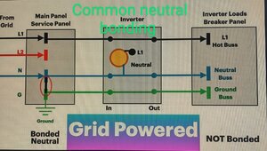
I found this great video and this "common neutral bonding" seems so simple and solves the problem apparently.

Common Neutral Bonding Grid Powered.jpgCommon Neutral Bonding Inverter Powered.jpg
 
The video makes it look easy. The inverter is passing N and G through. L1 out of inverter comes from the grid or from the inverted battery. The inverter load has a bonded N-G in both cases. Here's the BUT; In your RV what happens when you unplug the shore cord? Answer; you've lost your bond.

And another thing, I don't think your inverter IN and OUT for N and G are direct connections as shown. I think there is some magic electronics involved as well.

Now my mental exercise. How does the inverter know the difference between a tripped shore power breaker, or if shore cord is unplugged? My inverter doesn't pass through so I can't play with mine. Here's some tests for you. Measure the AC voltage of the inverter N IN to N OUT, Measure G IN to G OUT, and measure N OUT to G OUT. Make the measurements while on shore power (pass through), then again with the breaker feeding the inverter off, and again with the shore cord unplugged.
 
Now my mental exercise. How does the inverter know the difference between a tripped shore power breaker, or if shore cord is unplugged? My inverter doesn't pass through so I can't play with mine. Here's some tests for you. Measure the AC voltage of the inverter N IN to N OUT, Measure G IN to G OUT, and measure N OUT to G OUT. Make the measurements while on shore power (pass through), then again with the breaker feeding the inverter off, and again with the shore cord unplugged.
Thanks for sticking with me on this, here are the measurements. I added one more at the end.

On shore power with Inverter set to utility first:
N in to N out 0v
G in to G out 0v
N out to G out 0v

On shore power with Inverter set to utility first but the breaker is off supplying the inverter:
N in to N out 6.2v
G in to G out 0v
N out to G out 6.3v

Inverter set to utility first but the breaker off and the shore power cord is disconnected:
N in to N out 6v
G in to G out 0v
N out to G out 6.2v

Inverter set to solar then battery first with the breaker off and the shore power cord is disconnected:
N in to N out 6.1v
G in to G out 0v
N out to G out 6.3v
 
And another thing, I don't think your inverter IN and OUT for N and G are direct connections as shown. I think there is some magic electronics involved as well.

With the unit off G IN to G OUT shows continuity, neutral does not.
 
So it seems that the inverter messes with the neutral while inverting. When running on shore power (pass through) is the only time the N-B bond is there. The simple fix would be a relay across the inverter input, using the normally closed contacts to make a N-G bond on the output side. If you don't have power coming from the shore, the relay contacts will make a bond.

That's the brute force method of relay logic that worked for my 40 year traffic signal maintenance career. I think using the program #38 and inverter contacts might be more elegant.
 

diy solar

diy solar
Back
Top