Here it is high res so people can read the text. Adobe not that "sketchy" though
looks like the forum resizes pngs now ;o
Thx for the picture
")
I agree with
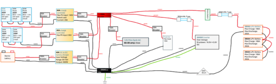
@0truck0 comments, that 100A cb between start battery and dc to dc needs to be 50A.
Also the battery cable negative from 3rd battery, yes.
Nice setup really!
All your issues are on that dc to dc.
1. 40A wires, I measured my Tacoma last night, that circuit is at least 30ft, those should be 4AWG to avoid voltage drop, and if you want to get the 40A ever.
2. What type dc to dc do you have, isolated or non-isolated? Probably non isolated, since in camper van the house and starter batteries and living and engine areas all share a chassis. This is critical, there should only be a SINGLE NEGATIVE TO GROUND BOND in the system! If your dc to dc is non isolated, probable, then your entire system is actually bonded through the start battery negative-to-chassis cable! You should not have a ground bond from your negative bus bar.
3. The ground from your inverter is probably incorrect and will make a ground loop and RF noise. When a metal cased component has a grounding point screw, like the inverter, it should be grounded to the chassis as close as possible to it's mounting point, like half inch away from its mount screws. However, if the inverter has a plastic case and there is zero ground path from its case to the chassis via mounting screws, like it sits on rubber washers and plastic case, THEN run a ground to a ground bus as shown, but don't bond it to negative. I say probably incorrect, because most inverters have metal case for heatsink and screw into some chassis mount usually...
Here is the reference doc from this site, for mobile grounding:


 om/id/urn:aaid:sc:us:b42c24bf-5fa1-4d74-b549-d9d9925f8ecf