diy solar

diy solar

Help with my Solar System

SethsVan

New Member
Joined
Mar 5, 2024
Messages
2
Location
Arkansas
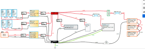
Newbie electrician here. I'm building a camper van with a solar electrical system. 1000W solar and 600aH lithium batteries. If anyone more experienced than me could let me know what I'm doing wrong, I would greatly appreciate it. I just don't want to catch my van on fire.

In addition to the picture, below is a PDF that includes links to the products I'm using.

https://acrobat.adobe.celectric system diagram.PNGom/id/urn:aaid:sc:us:b42c24bf-5fa1-4d74-b549-d9d9925f8ecf
 
Newbie electrician here. I'm building a camper van with a solar electrical system. 1000W solar and 600aH lithium batteries. If anyone more experienced than me could let me know what I'm doing wrong, I would greatly appreciate it. I just don't want to catch my van on fire.

In addition to the picture, below is a PDF that includes links to the products I'm using.

https://acrobat.adobe.cView attachment 200318om/id/urn:aaid:sc:us:b42c24bf-5fa1-4d74-b549-d9d9925f8ecf
Can you just take a picture of your setup and post that, so you don't force everyone to go through Acrobat.adobe.com? Or just attach a pdf? But NOT via some app website... that is really sketchy.
 
Nothing jumping out at me except how the batteries are wired. It works, but are you connecting 3 batts all parallel 12v?
You drew pos and neg connected to only one battery that goes to bus bar, then just connected the others down the line. That does work.

Better way is to connect neg to the 3rd battery and the pos to the first battery so the voltage draws through all 3 batteries, not just off the first, which then draws off the second, which then draws off the third. Is minimal difference, but the first battery is getting used more than the other two in your pic.

I would connect to the alternator or the starter motor rather than the car/van battery for the positive. If the starter motor is closer to your bus bar then is a good point to connect because the starter is not being used while driving and also has a very big wire going to it already and the positive lug is just there for the taking already.
Connecting to a lead acid battery terminal means future corrosion.
Wherever u connect I would fuse it as close to the power source as possible. You have a 40 amp DC-DC so I would not use 100 amp breaker before that, but a 50amp breaker. Just swap for the 50 on the other side of the DC-DC.

Looks like your breakers from 3 panels to controller are 30 amp, but panels 33 amp? Or is the math different, Im not sure how yours is... You may never see max rated output, but have a higher amp breaker than the panels are rated for. I would just switch the breakers on either side of the controller - on both controllers. I

I think I have mine set up similar with breakers on either side of the charge controller, except I use my controller to supply to the fuse box so the controller can shut down at low voltage (the battery will too, but the controller I can program myself), with the exception that the DC fridge runs directly off the battery terminals (after the breaker).
This allows you to disconnect the solar panels before disconnecting the battery by just tripping the breaker, then the reverse when done.
 
Last edited:

Attachments

  • pngquant-downsize-fs8.png
    pngquant-downsize-fs8.png
    381.9 KB · Views: 3
Here it is high res so people can read the text. Adobe not that "sketchy" though

looks like the forum resizes pngs now ;o
Thx for the picture:)
I agree with @0truck0 comments, that 100A cb between start battery and dc to dc needs to be 50A.
Also the battery cable negative from 3rd battery, yes.

Nice setup really!

All your issues are on that dc to dc.
1. 40A wires, I measured my Tacoma last night, that circuit is at least 30ft, those should be 4AWG to avoid voltage drop, and if you want to get the 40A ever.
2. What type dc to dc do you have, isolated or non-isolated? Probably non isolated, since in camper van the house and starter batteries and living and engine areas all share a chassis. This is critical, there should only be a SINGLE NEGATIVE TO GROUND BOND in the system! If your dc to dc is non isolated, probable, then your entire system is actually bonded through the start battery negative-to-chassis cable! You should not have a ground bond from your negative bus bar.
3. The ground from your inverter is probably incorrect and will make a ground loop and RF noise. When a metal cased component has a grounding point screw, like the inverter, it should be grounded to the chassis as close as possible to it's mounting point, like half inch away from its mount screws. However, if the inverter has a plastic case and there is zero ground path from its case to the chassis via mounting screws, like it sits on rubber washers and plastic case, THEN run a ground to a ground bus as shown, but don't bond it to negative. I say probably incorrect, because most inverters have metal case for heatsink and screw into some chassis mount usually...

Here is the reference doc from this site, for mobile grounding:
 

Attachments

  • Grounding Basics 4 - Mobile Grounding.pdf
    428.2 KB · Views: 1
Back
Top