diy solar

diy solar

How much voltage drop at 100A discharge?

davetelling

New Member
Joined
Nov 3, 2023
Messages
4
Location
Carson City NV
I am just starting out with a 280AH LiFePO4 battery, after having used some flooded lead-acid for a couple of years. I've looked online to see if I could find some info on how low the battery terminal voltage should drop under load, but haven't found anything other than generalities. With a fully charged battery, what should I expect to measure at the battery terminals when I connect a 100+A load? It seems to go lower than I would expect. The battery started at 13.38 volts. I turned the inverter on, set the heater load to high, and showed 135A draw from the battery. the voltage at the battery dropped to 12.5 volts after about 60 seconds, then after another 60 seconds, dropped to 12.48 volts. I turned the heater to the medium heat setting, and the current dropped to 85 amps, the battery voltage then rose to 12.7 volts. At this point, I watched the voltage for about 30 seconds, then shut everything off. The battery voltage rose fairly quickly to about 13.2 volts, then continued to rise to 13.26 volts after about 5 minutes. I went back inside, but noticed that the battery voltage was still slowing creeping upward.
So, does this seem normal? The only comparison I have is with two paralleled 85AH flooded lead-acid cells, and under about the same conditions, dropped from 12.7 to 11.8 volts with the same load.
 
The behavior is very normal. The creep slows to a crawl.

Too many variables to answer the subject question accurately, but we can work backwards.

The cells, bus bars, wires, terminals, etc., all have resistance and contribute to voltage drop.

Your resistance is determined by:

V = I * R
V = about 0.6V (12.7 to 13.3V)

R = V / I

R = 0.6V / 100A = 6mΩ - this is about equal to a large, very high quality brand new FLA battery AT the terminals.

Have you verified that all connections are properly torqued?
 
The nominal voltage / cell for Li is 3,2v on the flat part of the curve. If you can get hold of the cell literature ( graphs ) you can interpret cell voltage corrected for current and temperature.
 
The behavior is very normal. The creep slows to a crawl.

Too many variables to answer the subject question accurately, but we can work backwards.

The cells, bus bars, wires, terminals, etc., all have resistance and contribute to voltage drop.

Your resistance is determined by:

V = I * R
V = about 0.6V (12.7 to 13.3V)

R = V / I

R = 0.6V / 100A = 6mΩ - this is about equal to a large, very high quality brand new FLA battery AT the terminals.

Have you verified that all connections are properly torqued?
Thanks for this - so, at 135 A the drop was to 12.5 volts, so (13.3-12.48)/135 = 6mOhms. Is that a typical internal resistance for 280AH LFE battery?
Connections are nice and tight. I'm measuring right at the battery terminals. I didn't try to measure at the inverter inputs, as I know that there will be drop due to cable resistance. I was mainly concerned about the voltage drop measured at the battery terminals under load.
 
The nominal voltage / cell for Li is 3,2v on the flat part of the curve. If you can get hold of the cell literature ( graphs ) you can interpret cell voltage corrected for current and temperature.
Yes, I understand that part, I was wondering about the voltage drop under heavy loads.
 
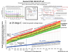
At 135 amps on 280 AH thick electrode cell, for a good cell, will be 80-120 millivolt slump after 1 to 3 minutes. Voltage measurement must be directly on cell terminals, not on top of bus bar nuts. If cells are colder than 15 degs C the slump will be greater.

Used cells over their lifespan will increase 3 to 5 times this voltage slump.

Wild card is your bus bar connections between cells. Good ones have about 0.17 milliohms cell terminal to cell terminal, yielding 135A x 0.17 milliohms = 0.023 volt drop for each bus bar in addition to cell terminal voltage slump. If you have nickel plated brass bus bars they are about 0.1 milliohm higher series resistance, then copper core bus bars, taking each cell terminal to cell terminal connection to 0.27 milliohms.

Assuming you are not including BMS series resistance drop in your 12.50v total. Expect about 0.5 milliohm for BMS.

Four cells x 110 millivolt slump, plus 3x 0.023 millivolt for bus bars at 135 amps equals approx. 0.512 volt slump at 135 amps.

0.440v + 0.069v = 0.512v total slump.

13.38v - 0.512v = 12.87v.LF280 overpotiential curve.png
 
At 135 amps on 280 AH thick electrode cell, for a good cell, will be 80-120 millivolt slump after 1 to 3 minutes. Voltage measurement must be directly on cell terminals, not on top of bus bar nuts. If cells are colder than 15 degs C the slump will be greater.

Used cells over their lifespan will increase 3 to 5 times this voltage slump.

Wild card is your bus bar connections between cells. Good ones have about 0.17 milliohms cell terminal to cell terminal, yielding 135A x 0.17 milliohms = 0.023 volt drop for each bus bar in addition to cell terminal voltage slump. If you have nickel plated brass bus bars they are about 0.1 milliohm higher series resistance, then copper core bus bars, taking each cell terminal to cell terminal connection to 0.27 milliohms.

Assuming you are not including BMS series resistance drop in your 12.50v total. Expect about 0.5 milliohm for BMS.

Four cells x 110 millivolt slump, plus 3x 0.023 millivolt for bus bars at 135 amps equals approx. 0.512 volt slump at 135 amps.

0.440v + 0.069v = 0.512v total slump.

13.38v - 0.512v = 12.87v.View attachment 176120
Wow! Thank you! That adds a lot more variables than I realized. I'll do another test now that I have the battery fully charged.
 
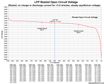
Make sure you take open circuit, rested cell voltage properly to get starting unloaded OCV. Usually 5 minutes of rest is enough but at low state of charge and above 3.35v after taking off charger, the time to equilibrium OCV will take longer to reach steady state.

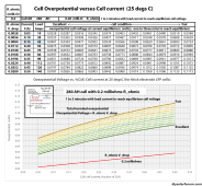
Open circuit voltage does not have too much temperature dependency, but overpotential voltage slump (bump for charging) with cell current is very dependent on temperature and gets much greater as cell temperature drops. Li-Ion batteries are not great for supplying high discharge current at cold temperatures as there will be greater terminal voltage slump. Cold temps inhibit lithum-ion migration within cell requiring higher overpotential overhead to push the required ion migration to meet the cell load current demand.

Chart below is rested open circuit voltage versus state of charge for LFP cells. Variance to chart numbers is less than 5 millivolts. Accuracy of your DVM may be the primary cause of variance to voltage reading. You really need a DVM with better than 0.05% DC voltage accuracy at 3.5 vdc. (+/- 0.05% accuracy at 3.5v is +/- 2 mVdc uncertainty). Number of digits displayed is DVM resolution, NOT its accuracy.

R_ohmic resistance of cell is primarily just conductor resistance of terminal connections to foil laminates, electrode to foil current collectors, and resistance of electrolyte. Its contribution is normally much less than the ionic overpotential voltage slump. If electrolyte dries out or is decomposed due to overcharging the R_ohmic will go up. Cell grows thicker protective Solid Electrolyte Interface (SEI) layer around negative electrode graphite over aging longevity of cell which increases cell R_ohmic resistance a bit as cell ages.

LFP Open Circuit Voltage vs SoC.png
Cell Overpotential Chart.png
 
Last edited:
Back
Top