


douglasheld
New Member
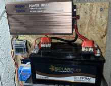
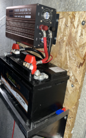
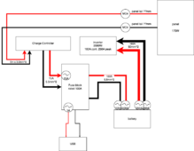
Hi all, I've recently set up a 2kW inverter with a single 130Ah battery and this is charged by a single 170W solar panel. The design purpose of my system is to allow occasional use of power tools or the shop-vac in my garage.
The original system I put together had poor quality cables bundled with the various equipment sets I bought on EBay. I evaluated with a thermal camera and decided that a number of improvements could be made.
I upgraded the inverter cables to 50mm^2 cables and learned to crimp the lugs. I've also added fusing, 2x2 MRBFs and an auto/marine fuse panel. The MPPT controller is now fused at 15A and I've upgraded the charger cables to 5.5mm^2.
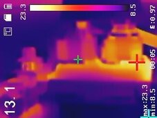
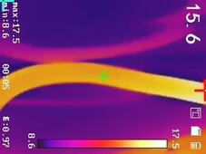
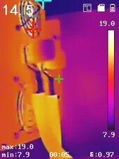
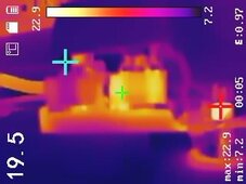
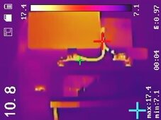
I have a shop-vac rated 1700W which I use as my test of the system. With this running on AC power provided by the inverter for 6 minutes, I recorded how warm the connections got with a thermal camera. I also recorded a voltage drop of 44mV across the red cable, and about 55mV across the black cable (during the 135A test).
Notice, in the thermal photos, the thicker PVC insulated cables are still getting a little warm, while the copper lugs stay cold. I also notice the fuse holder busbar gets a little warm. I've snugged the nuts but not torqued them, due to the tall posts being longer than my deepest 14mm socket.
My requests are:
The original system I put together had poor quality cables bundled with the various equipment sets I bought on EBay. I evaluated with a thermal camera and decided that a number of improvements could be made.
I upgraded the inverter cables to 50mm^2 cables and learned to crimp the lugs. I've also added fusing, 2x2 MRBFs and an auto/marine fuse panel. The MPPT controller is now fused at 15A and I've upgraded the charger cables to 5.5mm^2.
I have a shop-vac rated 1700W which I use as my test of the system. With this running on AC power provided by the inverter for 6 minutes, I recorded how warm the connections got with a thermal camera. I also recorded a voltage drop of 44mV across the red cable, and about 55mV across the black cable (during the 135A test).
Notice, in the thermal photos, the thicker PVC insulated cables are still getting a little warm, while the copper lugs stay cold. I also notice the fuse holder busbar gets a little warm. I've snugged the nuts but not torqued them, due to the tall posts being longer than my deepest 14mm socket.
My requests are:
- Sanity check the measured power losses in this system.
- Sanity check the fuse sizes compared to ampacity of the cables.
- In particular, I recognize I've chosen the wrong cable size for the connection from battery to the fuse board. It has M5 screw terminals, and I think I can get lugs to fit up to 25mm cable. Is that a sensible size for that link?
| Cable / connector | Description | Temperature under 135A load / 6 minutes at 9˚C ambient | Upgraded from |
| Battery terminals | lead SAE terminal posts | maybe 14˚C | - |
| Battery fuses | dual MRBF holders on each + and - | negative busbar gets 23C | no fuses |
| Fuse for inverter path | cube, 250A for each + and - paths | 20C | no fuses |
| inverter cables | 50mm^2 copper | 17-18˚C | 16.8mm^2 copper (2 x 8.4mm^2) |
| Fuse for fuse panel path | cube, 100A for each + and - paths | not load tested | no fuses |
| Cables to fuse panel | 5.5mm^2 copper | not load tested | nothing - no fuse panel |
| Charging circuit fuse | blade fuse, 15A | not load tested | no fuse |
| Charging cable | 5.5mm^2 copper | not load tested | 2.5mm^2 cable direct to MPPT charge controller |
Attachments
-
 v2 Front.png2.3 MB · Views: 15
 -
 v2 right.png1.3 MB · Views: 4
 -
 negative MRBF busbar 23C.jpeg19.4 KB · Views: 3
 -
 negative cable 16-18C.jpeg17.9 KB · Views: 1
 -
 inverter inputs and 50mm cables approx 16C.jpeg65.6 KB · Views: 1
 -
 positive MRBF 20C. something 23Cjpeg.jpeg19.7 KB · Views: 1
 -
 overall system after test.jpeg18.5 KB · Views: 3
 -
 Electrical Panel v2.png52.6 KB · Views: 4