


douglasheld
New Member
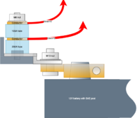
I've got a battery with SAE lead battery terminal posts that I want to protect with MRBF "cube" fuses. Since the primary purpose of these is to reduce the risk of a metal tool short-circuiting the battery terminals, I intend to fuse both the positive and negative terminals.
Obviously, I want to minimize the case where a tool touches two different unfused conducting surfaces - so I want to reduce those exposed surfaces as much as possible.
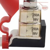
I will tell you what I do not like about these MRBF designs. The fuse holders come with silly little rubber caps for the insulated post, which is already fused. But, there is no safety for the big unfused busbar that runs the length of the device.
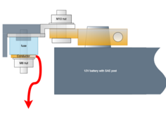
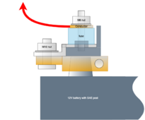
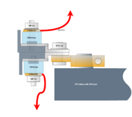
I'm thinking of the various ways the MRBF fuse assembly can be attached to battery posts, and how any available rubber boots can help as well. My palette includes:
My two questions are:
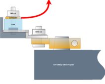
1. I think the minimum exposed unfused surface is Option 3, where I attach the clamp relatively high up on the post, and then rotate the MRBF holder back over the top of the post. Is there any inherent risk in doing that?
2. Considering the different possibilities, which rubber boots are available that could maximally protect the unfused surfaces? I didn't find any rubber boot designed for these things.
| "B" end of the tool contacts unfused conductor | "B" end of the tool contacts fused conductor | |
| "A" end of the tool contacts unfused conductor | catastrophic | a fuse will blow |
| "A" end of the tool contacts fused conductor | a fuse will blow | one of the fuses will blow |
Obviously, I want to minimize the case where a tool touches two different unfused conducting surfaces - so I want to reduce those exposed surfaces as much as possible.
I will tell you what I do not like about these MRBF designs. The fuse holders come with silly little rubber caps for the insulated post, which is already fused. But, there is no safety for the big unfused busbar that runs the length of the device.
I'm thinking of the various ways the MRBF fuse assembly can be attached to battery posts, and how any available rubber boots can help as well. My palette includes:
- https://www.amazon.co.uk/dp/B08LQPCJH5 tinned copper SAE post clamp with M10 post
- https://www.amazon.co.uk/dp/B0CNQ9QQ1Z MRBF fuse holders, with 100A for the fuse panel and and 150A to the inverter.
- rubber boots: ??? I have failed to find anything I'm sure would fit
My two questions are:
1. I think the minimum exposed unfused surface is Option 3, where I attach the clamp relatively high up on the post, and then rotate the MRBF holder back over the top of the post. Is there any inherent risk in doing that?
2. Considering the different possibilities, which rubber boots are available that could maximally protect the unfused surfaces? I didn't find any rubber boot designed for these things.
Attachments
Last edited:
")