100% agree. I good BMS will not drain your 100AH batteries in the slightest. Something else is in play here, or the Daly is defective.From the Overkill manual FAQ:
Q: What is the quiescent current? What can I do for long-term storage?
A: The quiescent current is as follows: (this was measured on a 4 cell BMS)
- ● 5.5 milliamps with everything off, when the BMS is active, but no bluetooth.
- ● 15 milliamps with the bluetooth active (after about 10 seconds it drops to 0.8 milliamps.
Reconnecting it wakes it up again).- ● 0.8 milliamps when the BMS is inactive.
So, assuming your battery setup is 100 amp hours, the BMS would run for 17 years. This proves that the BMS can be connected for long periods of time without any fear of it draining the battery.
Unplugging the balance connector would ensure complete shutdown
NOTE: The cell’s self-discharge rate will always cause the battery to drain over time, which may be several percent per month. This is simple chemistry and physics; there’s nothing that you or the BMS can do to avoid the battery cells from self-discharging over time, other than to occasionally top up the batteries.
You are using an out of date browser. It may not display this or other websites correctly.
You should upgrade or use an alternative browser.
You should upgrade or use an alternative browser.
I accidently deep discharged my LiFePo4 prismatic cells
- Thread starter merlin077
- Start date
My guess is the Heltec Baöan100% agree. I good BMS will not drain your 100AH batteries in the slightest. Something else is in play here, or the Daly is defective.
littleharbor2
Solar Addict
A dc clamp meter is real handy for troubleshooting this kind of stuff.
I have one - didn‘t had to use it cause the Heltec balancer did a good job until it effed upA dc clamp meter is real handy for troubleshooting this kind of stuff.
Just a quick update: 8 out of 16 cells are charged to 3.2V now without any issues. The internal resistance meter arrived and all 8 cells are measuring 0.40mOhm each. Doesn‘t sound too bad?
Edit: The 8 uncharged cells rest at 2.1V and also measuring 0.40-0.44mOhm each…
Edit: The 8 uncharged cells rest at 2.1V and also measuring 0.40-0.44mOhm each…
I use Heltec balancers on my builds and have ever had an issue.My guess is the Heltec Baöan
Just curious, did you raise the voltage in steps and if so what voltage did you start charging at?
I have just collected my RV after 4 months and both my two 208Ah batteries have discharged. One to 10.8v and the other 9.8v with plenty of cell divination and the lowest cell down to 2.344v. I only had the Dally BMS connected with the inverter and solar controller both turned off.
When I left the van both batteries were at 13.3v with all cells at the same volatage. Idrive back home today so wil recharge them tomorrow.
Hey, sorry for the delay!Just curious, did you raise the voltage in steps and if so what voltage did you start charging at?
I have just collected my RV after 4 months and both my two 208Ah batteries have discharged. One to 10.8v and the other 9.8v with plenty of cell divination and the lowest cell down to 2.344v. I only had the Dally BMS connected with the inverter and solar controller both turned off.
When I left the van both batteries were at 13.3v with all cells at the same volatage. Idrive back home today so wil recharge them tomorrow.
Initially i set the power supply to 2.5V and 0.2A and let it rest until current drops. Then I ramped up the voltage to 3.2 and 0.2A, same deal… After the current draw reduces, i set the power supply to 3.5V and betweeen 0.8 and 2.5A current to charge them fully.
The first cells were charged with quite little power, which obviously takes forever. After i was more confident that nothing will catch fire, i used more charge current
Between the charging phases I took regular swelling measurements with a caliper and monitored the internal resistance. The swelling went back a few mm, which is good i think
Next step is to discharge one of those cells with a 10A programmable load and hope we get a usable amount of energy out of them without setting something on fire…
No need to apologise as it seems like you have enough on your plate. Hope it all works out for you.
I need to do some tests on the Daly BMS to see how much they drain the batteries and why they didn’t shut down when reaching low voltage. At 0.2A it will take forever on yours. As mine are 280Ah batteries I just put 2A in to take the individual cells up to 2.5v and then raised it to 5A to take them up to 3.2v. Next I will put the cells in parallel to take them up to 3.6v.
With the one battery, although it was only down to 10.8v the delta was 900mv. I put 12A of solar into it and was pleasantly surprised to see the BMS balancing and at the end of the day the battery sitting at 13.2v with a 7mv delta. After seeing such a variation in the cell voltages of both batteries I think I will top balance them again.
nt40lanman
New Member
- Joined
- Aug 13, 2022
- Messages
- 22
That's very encouraging. You may still get some usefulness out of them.
Tim Tim, in the automotive biz, 200ma or 0.2a is too much draw. I would imagine it's the same here.
Tim Tim, in the automotive biz, 200ma or 0.2a is too much draw. I would imagine it's the same here.
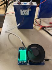
Just a quick test of the chinese 150W load. Whoever wrote that „UI“ for the frontend must have a faible for Acid while at work ? Unfortunately it doesn’t provide RS232, so no logging and nice graphs.
And yes, i need proper cabling, because of the BBC quite significant voltage drop. Those flimsy gauge wires are not made for 10A continous power draw
The whole experiment will take place in the garage for three reasons:
The fan is quite a bit annoying, i don‘t wanna burn the house down in case something begins to die and last but not least there is a good motivation to clean up the garage
I think 10A as test current will be suitable as it‘s well within spec. If something goes wrong at this low current, then better under controlled circumstances.
I‘m really really curious how much capacity the cells can deliver!

RCinFLA
Solar Wizard
- Joined
- Jun 21, 2020
- Messages
- 3,565
Just an fyi, 1 kHz battery impedance meter is not the best indicator of ionic migration resistance, which is primarily what electrolyte decomposition effects.
Mostly what you are measuring with a 1 kHz impedance meter measurement is conductive resistance of cell (mostly metal interconnects). The most prevalent damage item the 1 kHz impedance meter will show up is increased resistance due to electrode material delamination from the copper foil current collector on the negative graphite anode side and LFP cathode material from the aluminum foil current collector on the positive electrode side.
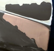
A little bit of bloating is not a disaster. Cells bloat during manufacturing charge forming process, but you typically do not see it because the manufacturer puts the pressure release port in after charge forming so the gas is allowed to escape before the cell is finally sealed up.
The visual gas bloating is not the really damaging part of electrolyte decomposition. The bad part of electrolyte decomposition is the hydro-carbon tars that are also biproducts of the electrolyte decomposition. These tars gum up the internal cell electrode material pores reducing the paths for lithium-ion migration. This results in a higher overpotential voltage (terminal voltage slump during discharge and terminal voltage bump during charging) necessary to get the lithium ions to move through the cells at a rate necessary to support the external demanded terminal current on the cell.
When you dissect a cell that has been severely overcharged with extreme bloating, when you unwrap the layers you will see the material which should be a uniformly flat black graphite colored electrode with a brownish haze color over it that is the hydro-carbon tar coating the electrode.
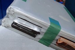
The cell wrap does not actually bloat. The top of the cell wraps are open to allow foil conductors to escape so gas just leaks out the top of the wrap laminates into the sealed outer metal container of cell. All you see is the bloated outside container. Usually, the bloating gas will eventually diffuse out through plastic terminal grommets in the metal casing. It may take a few weeks to a few months to totally deflate. You never want a burst pressure port however. That will allow electrolyte to eventually evaporate from cell.
Mostly what you are measuring with a 1 kHz impedance meter measurement is conductive resistance of cell (mostly metal interconnects). The most prevalent damage item the 1 kHz impedance meter will show up is increased resistance due to electrode material delamination from the copper foil current collector on the negative graphite anode side and LFP cathode material from the aluminum foil current collector on the positive electrode side.

A little bit of bloating is not a disaster. Cells bloat during manufacturing charge forming process, but you typically do not see it because the manufacturer puts the pressure release port in after charge forming so the gas is allowed to escape before the cell is finally sealed up.
The visual gas bloating is not the really damaging part of electrolyte decomposition. The bad part of electrolyte decomposition is the hydro-carbon tars that are also biproducts of the electrolyte decomposition. These tars gum up the internal cell electrode material pores reducing the paths for lithium-ion migration. This results in a higher overpotential voltage (terminal voltage slump during discharge and terminal voltage bump during charging) necessary to get the lithium ions to move through the cells at a rate necessary to support the external demanded terminal current on the cell.
When you dissect a cell that has been severely overcharged with extreme bloating, when you unwrap the layers you will see the material which should be a uniformly flat black graphite colored electrode with a brownish haze color over it that is the hydro-carbon tar coating the electrode.
The cell wrap does not actually bloat. The top of the cell wraps are open to allow foil conductors to escape so gas just leaks out the top of the wrap laminates into the sealed outer metal container of cell. All you see is the bloated outside container. Usually, the bloating gas will eventually diffuse out through plastic terminal grommets in the metal casing. It may take a few weeks to a few months to totally deflate. You never want a burst pressure port however. That will allow electrolyte to eventually evaporate from cell.

Last edited:
RCinFLA
Solar Wizard
- Joined
- Jun 21, 2020
- Messages
- 3,565
If I read the load test screen correctly it looks pretty bad with 3.13v and only 51 AH's out of cell at 6 amp load. Problem you have is the tester does not have remote voltage sensing, so the voltage drop on the wires are significant to what the tester reads for cell voltage. Check voltage at battery terminals with a DVM compared to what tester says. You will likely find at the cell terminals the voltage will be significantly higher voltage.
I use a DL24P with four wire connections to bring remote cell voltage measurement directly to cell terminals and prevent the load current carrying wires voltage drop from impacting cell voltage reading on the tester.
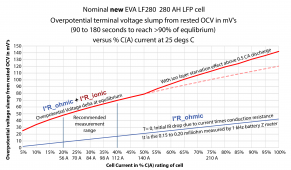
6.2 amps discharge rate is not enough to show much overpotential voltage slump on a 105 AH cell. You really need at least 20 amps discharge rate for a good test on cells. I have modified my DL24P with two more MOSFET load/heat sinks to achieve 50 amps load test for 280 AH cells.
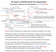
This graph is for a new 280 AH EVE cell but you can scale it by C(A)%. 105AH/280AH load current for same terminal voltage slump. A cell will increase in overpotential slump terminal voltage by 3x-5x over its lifetime.


Last edited:
Similar threads
- Replies
- 16
- Views
- 865
- Replies
- 0
- Views
- 267
- Replies
- 5
- Views
- 757


