mike616
New Member
I am trying to connect my EG4-LL (24V) batteries to Solar Assistant. I have two questions that I cannot figure out.
1. How do I wire up an ethernet cable to the RS485-to-USB adapter?
2. Given the EG4's wonky DIP switch issues, how can I be sure I'm on the right address (address 2 per Solar Assistant's guide).
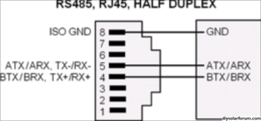
For question 1, I've followed this image:

I am wiring port 5 to the A+ terminal, 4 to the B- terminal, and 8 to the GND terminal. I've also tried flipping 4 and 5. I get nothing from the batteries in Solar Assistant or in EG4's BMS Tools.
I've also tried using this cable with the same results.
For question 2, I have no way to know what DIP setting I'm supposed to be on for my first battery. Multiple posts on here say that people have their DIP switches flipped or mirrored. I've tried the following permutations of address 2 and got nothing:
1 2 3 4
D U D D
D D U D
U U D U
U D U U
Is there any reliable way to determine what address the battery BMS thinks it's on? I don't see anything in the limited LCD screen options. I've tried using `minicom` on my Linux machine and BMS Tools in a Windows VM and just nothing at all.
I've been at it for three days now and have idea what to try next. Please help!
1. How do I wire up an ethernet cable to the RS485-to-USB adapter?
2. Given the EG4's wonky DIP switch issues, how can I be sure I'm on the right address (address 2 per Solar Assistant's guide).
For question 1, I've followed this image:

I am wiring port 5 to the A+ terminal, 4 to the B- terminal, and 8 to the GND terminal. I've also tried flipping 4 and 5. I get nothing from the batteries in Solar Assistant or in EG4's BMS Tools.
I've also tried using this cable with the same results.
For question 2, I have no way to know what DIP setting I'm supposed to be on for my first battery. Multiple posts on here say that people have their DIP switches flipped or mirrored. I've tried the following permutations of address 2 and got nothing:
1 2 3 4
D U D D
D D U D
U U D U
U D U U
Is there any reliable way to determine what address the battery BMS thinks it's on? I don't see anything in the limited LCD screen options. I've tried using `minicom` on my Linux machine and BMS Tools in a Windows VM and just nothing at all.
I've been at it for three days now and have idea what to try next. Please help!


