diy solar

diy solar

I think I failed at pre-charge resistor?

Rednecktek

Solar Wizard
Joined
Sep 8, 2021
Messages
5,589
Location
On a boat usually.
Can someone tell me why this isn't working please?
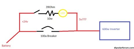
Precharge Fail.jpg

I press the button and the light comes on but both the inverter and my DMM show only 5v getting through. Once I step this up to the 3Kw 24v Growatt the pre-charge is going to take all bloody week!

What am I missing? Wrong resistor? Wired wrong? Help?!?!
 
Can someone tell me why this isn't working please?

View attachment 167463

I press the button and the light comes on but both the inverter and my DMM show only 5v getting through. Once I step this up to the 3Kw 24v Growatt the pre-charge is going to take all bloody week!

What am I missing? Wrong resistor? Wired wrong? Help?!?!


I used a 48v testlight bulb the other day on my friend's dual Quattro system, it measured about 91 Ω on my multimeter. Do you have a second resistor or light bulb to wire in parallel to see if it can make it flow enough more current to catch up to the inverter caps including drain?

Also make sure the inverters are turned off so they aren't trying to pull full idle draw to run the precharge circuit, or it will never be able to catch up and balance down to zero...

Before I came over to help, my friend had initially been trying to charge both of his Quattros while the inverter switches were turned on, so it could never catch up and balance to zero until shutting the inverters off.

If it's catching up, the light should get dimmer, and dimmer, and dimmer, until it goes out completely, then you can close your breaker... That's why I like using a light instead of a resistor, because it gives a visual indication of progress, and you know it's ready to enable the main connection once the light goes out.
 
Last edited:
With my 48v inverter, i didn't use a precharge resistor (i don't own one).

I tapped it on the 12v positive, then 24v positive, then 36v positive, then 48v positive and all was well :)
 
With my 48v inverter, i didn't use a precharge resistor (i don't own one).

I tapped it on the 12v positive, then 24v positive, then 36v positive, then 48v positive and all was well :)

I generally don't bother either with a precharge resistor, well I will use something if I have it available, but in the case with my friend with the Quattros who had the Trophy battery shelves, the excessive current kept tripping the BMS so it could not stay on by the time the power was connected, even when we had it almost precharged (light was really dim and it didn't even visibly spark), it still kept tripping the BMS, was super sensitive, we had to wait until the precharge testlight was completely not illuminated at all, and hook the power up before removing the testlight before the battery module would stay on without tripping the BMS.

Another way I use on the bench when I'm working on fixing friend's packs, is I use a bench power supply and sync the voltages first, before I bring the power leads together to avoid spark. You can put the power supply onto the inverter side, then turn it up to the same voltage as the battery is at (while is connected to the inverter), and then connect the breaker or wire up to the battery and no spark, essentially does the same thing as precharge with a light, except we're just using a different power source to neutralize the voltage differential.
 
Last edited:
You will have voltage drop across resistor + lamp so you can't have 24V both sides. Precharge is just to fill up the capacitors and once the lamp is off, turn on the breaker. As mentioned, the inverter needs to be off.

Generally, precharge is done when connecting cables. With your permanently wired breaker you can probably not precharge. Issue could be tripping BMS due to amp surge but you can only try.
 
I used a 48v testlight bulb the other day on my friend's dual Quattro system, it measured about 91 Ω on my multimeter. Do you have a second resistor or light bulb to wire in parallel to see if it can make it flow enough more current to catch up to the inverter caps including drain?
Yes, the resistor was a 2-pack, I'll throw the other one in there tomorrow and see if that helps. Should the light bulb be in parallel as well or everything in series?
Also make sure the inverters are turned off so they aren't trying to pull full idle draw to run the precharge circuit, or it will never be able to catch up and balance down to zero...
Gotcha!
Before I came over to help, my friend had initially been trying to charge both of his Quattros while the inverter switches were turned on, so it could never catch up and balance to zero until shutting the inverters off.

If it's catching up, the light should get dimmer, and dimmer, and dimmer, until it goes out completely, then you can close your breaker... That's why I like using a light instead of a resistor, because it gives a visual indication of progress, and you know it's ready to enable the main connection once the light goes out.
That's what I was hoping to see but after 3 minutes the light wasn't any dimmer on a 600w inverter.
 
Last edited:
You will have voltage drop across resistor + lamp so you can't have 24V both sides. Precharge is just to fill up the capacitors and once the lamp is off, turn on the breaker. As mentioned, the inverter needs to be off.

Generally, precharge is done when connecting cables. With your permanently wired breaker you can probably not precharge. Issue could be tripping BMS due to amp surge but you can only try.
I need to be able to completely secure the power to the system, it's for a cabin out in NE Washington and upwards (and over now) a year between visits. The design ins that this will connect between both terminals of the breaker as a "bypass" to charge up the inverter before I power it on via the main 150a breaker.
 
I need to be able to completely secure the power to the system, it's for a cabin out in NE Washington and upwards (and over now) a year between visits. The design ins that this will connect between both terminals of the breaker as a "bypass" to charge up the inverter before I power it on via the main 150a breaker.

You could try some light bulbs too.. I bought a 10 pack of these..


I actually did test these on 24v and 48v, and it still lights up a little dimmer on 24v, or can actually look for a similar bulb spec'd at 24v, like for a 24v excavator or commercial truck which certain models have 24v systems. Or just put a couple of the 48v bulbs in parallel to pull more amps. You just have to get the watts flow up higher than the 'inverter-off' capacitor circuit bleed-down rate (I just made up that term, maybe it's called something else), but it's the rate at which the caps bleed back down to zero when you pull the power off of it.
 
Last edited:
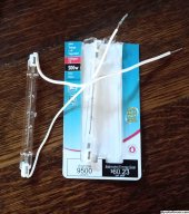
Here is a cheap solution. You can buy these for as low as 99 cents a pair. No need for a socket, the ends are stainless which easily takes colder. attach some wires and heat shrink the ends. These 500W ones are about 2 ohms cold, put two in series. About 10-15 ohms when they heat up. They will glow with just 12V.

500W_T3s.jpg
 
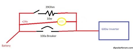
Figured it out! For some reason having the LED in series was causing the hangup. I threw it in parallel with the resistor and everything worked great!
Yeah, this is what I was going to say, that LED isn't going to flow enough current to allow the inverter to precharge. I'm actually amazing the LED didn't fail in the process.

Glad you got it figured out.
 
I just looked at the original diagram and saw LED and was hoping it was an actual filament light bulb, but apparently you got it figured out in the end.
 
Back
Top