diy solar

diy solar

INLINE FUSE For panels

tomy2

escape artist
Joined
Mar 12, 2022
Messages
432
Location
paso robles ca.
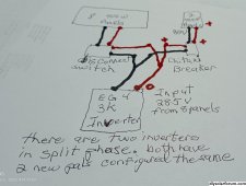
Adding two 400 watt panels to an off-grid system, for extra winter watts. Wanted to install a 20 amp inline fuse to the positive cable, but the MC4 fuse connector shows the current flow from the inverter back to the panels. Not what I expected. If installed that way, will it work? or did I just buy the wrong fuse?
 
Sounds like a blocking diode.
Not a fuse.
Are you sure that you bought the right thing?
 
Sounds like a blocking diode.
Not a fuse.
Are you sure that you bought the right thing?
this is what they are; I don't understand why the flow arrow is pointing back at the panels.

Pvfarosh 20A Solar Fuse Holder Connector IP68 Waterproof 1000V in-line Fuse Holder 20A Male and Female Connector Waterproof in-Line Fuse Holder (Contains 4 fuses + 2 Solar Fuse Holders)… (20A)​

 
The in-line fuses I have have no arrow on them and I checked with multi meter, there is no diode installed, just a 20A fuse

IMG_20231113_062710650.jpg

Can you post a picture of your fuse ?
Have you checked with multi meter if it has a diode ?
 
The in-line fuses I have have no arrow on them and I checked with multi meter, there is no diode installed, just a 20A fuse

View attachment 177504

Can you post a picture of your fuse ?
Have you checked with multi meter if it has a diode ?
how would a meter show a diode? mine has a fuse inside, could it be both. their diagram shows one on the positive and one on the negative. the arrow on the second one is probably pointing the opposite way, but right now , it's too cold outside for me to check it .
 
how would a meter show a diode? mine has a fuse inside, could it be both. their diagram shows one on the positive and one on the negative. the arrow on the second one is probably pointing the opposite way, but right now , it's too cold outside for me to check it .
Eg:
Do you have a link to the fuse you bought ?
The title you posted ( i assume you used copy&paste) does not mention the word diode.
*update*
If it is this fuse: https://www.amazon.com/Pvfarosh-Connector-Waterproof-Holder-Female/dp/B08S3JD72T I doubt there is a diode in it.
 
1699888473271.pngthe online picture doesn't show the arrow. I didn't see a diode inside only a fuse. I wonder if the arrow is to indicate which line they want you to put it on. I only want one on the red cable. if it is only a fuse, it should not matter what direction it faces.
 
Not sure what this pic means. I don't see anything inside that looks like a diode
If you have a meter, I would just check it to be sure.
The meter will read OL in one direction and close to zero the other way. (Set for resistance or continuity)
If it has a diode in it.
If not, it will read the same, either way.
 
If you have a meter, I would just check it to be sure.
The meter will read OL in one direction and close to zero the other way. (Set for resistance or continuity)
If it has a diode in it.
If not, it will read the same, either way.
It tested as a fuse, but I haven't used it yet. When the panels were hooked up, the inverter panel input dropped from 280v to zero. The new panels are reading 85v at the breaker and where they connect to the splitter. When I tried shutting down the original panels and just using the new panels, the inverter reads zero volts. I even switched splitters and nothing. Here is one of my crude diagrams. What should I try next?
 

Attachments

  • new panels.jpg
    new panels.jpg
    915.7 KB · Views: 6
You are putting 8 panels in parallel with 2 panels?
That's not going to work out well, at all.
The two strings need to be similar in voltage.
 
You are putting 8 panels in parallel with 2 panels?
That's not going to work out well, at all.
The two strings need to be similar in voltage.
I wasn't thinking in terms of strings. I see your point. Probably should put them in series with the other 8.
Edit; why would the two new panels show no inverter volts when the original panels were off? not enough volts?
 
Last edited:
I wasn't thinking in terms of strings. I see your point. Probably should put them in series with the other 8.
Are they facing the same direction and angle?
Would 10 be in the correct VOC safety range?
 
Are they facing the same direction and angle?
Would 10 be in the correct VOC safety range?
the EG4 says 500V max, these all would only do 450V max. They both face south, but these are flat and the others are at about 25 degrees. The new ones are bifacial too and will get some light from below.
 
the EG4 says 500V max, these all would only do 450V max. They both face south, but these are flat and the others are at about 25 degrees. The new ones are bifacial too and will get some light from below.
Not the best setup. But a lot better than 8 and 2.
 
What about adding micro inverters or something to the new panels. I'm not familiar with how they function.
 
Micro inverters are for a grid-tied system.
They need to see a grid source to operate.
 
Back
Top