


OK So I bought a bunch of the JBD BMSs for my powerwall and needed a way of monitoring/managing them that did not require I walk to the solar room with my cell phone and connect to each one with bluetooth or worse yet somehow come up with a 14 serial connection system to my raspberry Pi. So I came up with a method to use the ESP8266 (ESP-01) chip to provide wifi access to my BMSs. I'm sharing my method here.
To duplicate, you'll need the following components:
PCB Boards:
Connectors for the UART
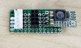
The BMS puts out 10-12v on the V pin of the uart, so we need a way to go to 3.3v for the esp-01:
If you don't have header pins, you'll need some to solder the voltage regulator to the PCB:
ESP-01s chips (prob dont need the 1M chips, but I have future plans for these yet):
A way to mount them:
A way to program them:
Also, you'll need to get esp-link to flash onto the ESP-01

 github.com
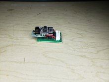
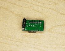
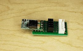
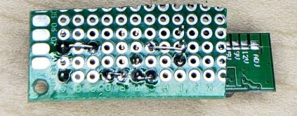
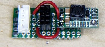
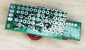
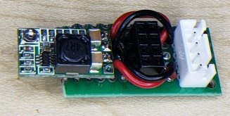
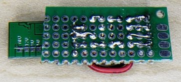
I'll go through the steps, but the end result looks like the attached pic
note: I've been considering drawing up plans for JLPCB and maybe 3D printing a case, but haven't had the time yet. For now, they work and work well.
To duplicate, you'll need the following components:
PCB Boards:
ELEGOO 32 Pcs Double Sided PCB Board Prototype Kit for DIY Soldering with 5 Sizes Compatible with Arduino Kits: Amazon.com: Industrial & Scientific
ELEGOO 32 Pcs Double Sided PCB Board Prototype Kit for DIY Soldering with 5 Sizes Compatible with Arduino Kits: Amazon.com: Industrial & Scientific
www.amazon.com
Connectors for the UART
Amazon.com: LATTECH 15 PCS 4 PIN JST XH Female Connector on Both Side - 100mm 1007 26 AWG & 30 PCS 4 PIN JST XH Male Connector : Electronics
Buy LATTECH 15 PCS 4 PIN JST XH Female Connector on Both Side - 100mm 1007 26 AWG & 30 PCS 4 PIN JST XH Male Connector: Connectors & Adapters - Amazon.com ✓ FREE DELIVERY possible on eligible purchases
www.amazon.com
The BMS puts out 10-12v on the V pin of the uart, so we need a way to go to 3.3v for the esp-01:
If you don't have header pins, you'll need some to solder the voltage regulator to the PCB:
OCR 20PCS 2.54mm Breakaway PCB Board 40Pin Male and Female Header Connector for Arduino Shield: Amazon.com: Industrial & Scientific
OCR 20PCS 2.54mm Breakaway PCB Board 40Pin Male and Female Header Connector for Arduino Shield: Amazon.com: Industrial & Scientific
www.amazon.com
ESP-01s chips (prob dont need the 1M chips, but I have future plans for these yet):
Amazon.com: Melife 4Pcs ESP8266 ESP-01S WiFi Serial Transceiver Module with 1MB Flash 3.3V for Arduino: Computers & Accessories
Amazon.com: Melife 4Pcs ESP8266 ESP-01S WiFi Serial Transceiver Module with 1MB Flash 3.3V for Arduino: Computers & Accessories
www.amazon.com
A way to mount them:
Amazon.com: Gikfun 2.54mm Pitch 2X4 8 Pin Female Double Row Straight Header PCB Connector (Pack of 50pcs) AE1174: Computers & Accessories
Amazon.com: Gikfun 2.54mm Pitch 2X4 8 Pin Female Double Row Straight Header PCB Connector (Pack of 50pcs) AE1174: Computers & Accessories
www.amazon.com
A way to program them:
Amazon.com: ESP-01S USB to ESP8266 ESP-01S Wireless Wifi Adapter Module Wi-Fi CH340G 4.5-5.5V, 115200 Baud Rate: Computers & Accessories
Buy ESP-01S USB to ESP8266 ESP-01S Wireless Wifi Adapter Module Wi-Fi CH340G 4.5-5.5V, 115200 Baud Rate: Network Adapters - Amazon.com ✓ FREE DELIVERY possible on eligible purchases
www.amazon.com
Also, you'll need to get esp-link to flash onto the ESP-01
GitHub - jeelabs/esp-link: esp8266 wifi-serial bridge, outbound TCP, and arduino/AVR/LPC/NXP programmer
esp8266 wifi-serial bridge, outbound TCP, and arduino/AVR/LPC/NXP programmer - jeelabs/esp-link
github.com
I'll go through the steps, but the end result looks like the attached pic
note: I've been considering drawing up plans for JLPCB and maybe 3D printing a case, but haven't had the time yet. For now, they work and work well.
Attachments
Last edited:


")


