Prof Chill
New Member
- Joined
- Apr 11, 2022
- Messages
- 15
I have a JK-B2A25S60P that I’m trying to puzzle my way through. Most of my electronics knowledge has come from building circuit boards for things like guitar pedals and stepper motors 20 years ago. I made a solar setup about 5 years ago, but it was fairly small and used lead acid batteries. The system I’m building will run a 20kw sailboat motor. I’m new to the LiFePo, high amp world.
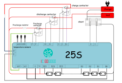
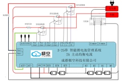
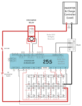
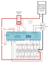
When I look at the diagram from the JK manual, it almost looks as if the yellow lead from the V- terminal goes directly into the B- terminal, bypassing the main battery negative, and that the B- lead goes to the battery side of the shunt. This can’t be correct, can it? Shouldn’t the V- and B- terminals both go to the negative battery terminal or negative bus?
I’m also wondering how to get the thing to start up. This BMS doesn’t seem to have the same wiring configuration as the other JK BMS’s without external contactors. How do I add the 9v battery in series to get the BMS to start up? What terminals do I cross with the leads from the 9v battery?
Amy help you can give me would be hugely appreciated. The documentation for it is really sketchy.


