diy solar

diy solar

JK BMS precharge adequate for Conext Pro 6.8KW?

scpanish

New Member
Joined
Jul 29, 2021
Messages
26
Location
NH, USA
Will my new Conext XW Pro 6.8KW inverter require a special precharge procedure to be connected to my LFP batteries? These are 2 paralleled batteries totalling 29KWH with the JK 200A smart BMSs. The BMSs allow maximum amperage to be set (default is 200 A) but I don't know if reducing that would work to limit the inrush current when I first connect the battery bank and inverter. Do the JKs have a precharge resistor? I do have a power resistor that I could use, or an old 60W 120V lightbulb.

I didn't take any special precautions when connecting the battery bank (configured for 24V) to my current Trace 4024, and I did get a small spark, but chances are the caps were still charged up.

Just looking for wisdom....thanks in advance!
 
Update. The XW Pro 6.8 is up and running. You definitely want to do a soft start, big inrush. I used a power resistor and initially held the power through it for a couple seconds. Then briefly touched the positive cable to the battery bus. Big spark. Repeated the power resistor contact for a few more seconds, the XW panel came on in "standby". Figured that was enough, opened the breaker, connected the cable to the bus through a 175A semiconductor fuse (extremely fast fuse), closed the breaker, and the fuse blew instantly. Connected through the power resistor this time for a good minute, the XW powered up, battery state lights came on, "event" light came on. Connected through a 400A fuse, closed the breaker and it worked with no additional drama. Works well, hums a bit loudly when there is a significant load, but it's in the cellar.
 
You must have missed it.

Pre-charge resistors are to be used with the inverter in the OFF position. The cap charge surge occurs even when the inverter is off.

  1. Inverter off.
  2. Pre-charge resistor between terminal and cable. Wait until battery voltage can be measured at inverter terminals.
  3. Remove resistor from circuit.
  4. Immediately position cable on terminal and secure/torque.
  5. Inverter on.
 
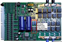
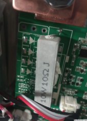
The JK active balance BMS 16/24 BMS has pre-charge resistors and pre-charging MOSFET but it is only for BMS initial activation to protect BMS. It limits initial surge to about 125 amps.

Once BMS is activated ON, it does not pre-charge if you open path to inverter with a circuit breaker then reconnect after inverter capacitors have discharged again.

Max current setting in BMS only limits maximum current drain before BMS disconnects discharge path showing an overcurrent error. The overcurrent limit is slow reacting on shutting off its MOSFET switches so it is not fast enough to stop high surge current when charging inverter input capacitors after BMS has been turned on. (or if you accidentally short circuit battery cables going to inverter).

Without additional external pre-charge resistance, the peak inverter capacitor charge current is 1000-3000 amps, lasting less than a millisecond, depending on your battery cabling path resistance, battery internal impedance, and size/ESR of inverter DC input path filter capacitors. It can pop wire bonding in some of the BMS MOSFET's.

16S full board pre-chg picture.jpg
Un
 
Last edited:
Pre-charge resistors are to be used with the inverter in the OFF position.
The XW usually turns on when you power it, they don't have any switch just a power button. If there is a way to avoid it, it has to be planned in advance by putting it in standby mode before removing power.

So practically, XW owners do need a precharge process that allows for power on. If you time it right you can precharge and then connect power before it goes on which takes a few seconds.
 
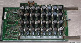
BTW, Xantrex XW pro has just about the most inverter DC input capacitance I have seen in LF inverters which generally have more capacitance than HF inverters.

XW also uses low ESR caps and a lot of them in parallel to keep the net effective ESR low.
Thirty-two 820 uF, 100 wvdc Nichicon in parallel. Total 26,240 uF at low ESR.

Typical Chinese 5 kVA HF inverter uses four cheap, higher ESR 4,700 uF, 63 wvdc caps in parallel. 63 wvdc rating caps are very marginal for a 48v inverter. Chinese are not known for designing in much margin. Bill of material costs are more important.

If I recall, XW gave EG4 rack batteries a lot of headaches.


XW battery Nichicon 820 uF 100vdc x32 capacitor board.jpg
 
All good info which should help folks in the future if they find this thread. I think the XW-Pro will be a great inverter, but I don't understand Schneider's failure to have a real power switch, or built-in precharge. Cheap to implement.

I am using two JK BMSs which I powered down before bringing on the new inverter, and since I had to reconfigure them from 24 to 48V, therefore removing the battery harness(es), I thought they would essentially be at a first-time power up. That was naive on my part, they kept old settings. So the built-in precharge didn't work. And I've never seen precharge mentioned anywhere but in the post above. There must be a factory reset somewhere but I didn't know about it....should have looked at the manual. I wasn't expecting the precharge time to be so long. I was using a 25ohm, 30watt resistor.
 
The JK active balance BMS 16/24 BMS has pre-charge resistors and pre-charging MOSFET
I'm sorry, but you are WRONG !
That resistors on BMS are not for pre-Charge.

They do not do any pre-Charge functions as you said !
 
I'm sorry, but you are WRONG !
That resistors on BMS are not for pre-Charge.

They do not do any pre-Charge functions as you said !
If you are going to quote me, quote the complete statement.

"The JK active balance BMS 16/24 BMS has pre-charge resistors and pre-charging MOSFET but it is only for BMS initial activation to protect BMS. It limits initial surge to about 125 amp.

Once BMS is activated ON, it does not pre-charge if you open path to inverter with a circuit breaker then reconnect after inverter capacitors have discharged again.
"
 
Hi,

All good info which should help folks in the future if they find this thread. I think the XW-Pro will be a great inverter, but I don't understand Schneider's failure to have a real power switch, or built-in precharge. Cheap to implement.

I am using two JK BMSs which I powered down before bringing on the new inverter, and since I had to reconfigure them from 24 to 48V, therefore removing the battery harness(es), I thought they would essentially be at a first-time power up. That was naive on my part, they kept old settings. So the built-in precharge didn't work. And I've never seen precharge mentioned anywhere but in the post above. There must be a factory reset somewhere but I didn't know about it....should have looked at the manual. I wasn't expecting the precharge time to be so long. I was using a 25ohm, 30watt resistor.

I ran in to this pre-charge problem with my new 11kW inverter, the original 5kW is OK. The JK BMS shut down immediately on "Short Circuit" protection. I did a bit of searching, and found a cheap and easy method by using 2 x 24V globes in series. These work great, they glow bright, then when the lights fade, the caps are charged. No guesswork required.

dRdoS7

EDIT:

I found the info here: https://thetechpapa.com/easy-way-to-pre-charge-a-48v-inverter/

Local auto parts had a pack of 2 single filaments cheap, so did it with those rather than 1 dual filament.
 
Last edited:
If you are going to quote me, quote the complete statement.

"The JK active balance BMS 16/24 BMS has pre-charge resistors and pre-charging MOSFET but it is only for BMS initial activation to protect BMS. It limits initial surge to about 125 amp.

Once BMS is activated ON, it does not pre-charge if you open path to inverter with a circuit breaker then reconnect after inverter capacitors have discharged again.
"
And you are again wrong!
"initial activation to protect" - it's just a juggling by words, it's not any precise technical statement.

That resistors + that mosfet (connected in series to the resistors) has no any relation to pre-charge technic at all!
If you would check PCB topology and think good enough, maybe you would understand it yourself.

Existence of such resistors+mosfet on a PCB does not automatically mean that it's pre-charge circuit.
 
You can smile as long as you want guys. But it does not change the fact that those 2 resistors + single mosfet are dedicated to keep discharge mosfets in a safe region as for Vds, when for some reason all discharge mosfets should trigger and interrupt the circuit under load.
To avoid huge voltage spike which may break mosfets.
Real scenario is - over current or short circuit protection cases.

So, this is not related to pre-charge scenarios in any way.
 
Back
Top