diy solar

diy solar

JK inverter BMS and Voltronic/Phocos Inverter communication

xristostsilis

New Member
Joined
Mar 24, 2022
Messages
127
Hi!

I am looking to buy one new jk inverter BMS. however my inverter is a Phocos 5kw 230v 48v system which is the same as a voltronic but just rebranded so anything that could apply into a voltronic could also work here.


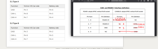
I want to know whether i can make the bms communicate with my inverter. my inverter does not support can bus protocol, only rs485 and it supports the pylontech over rs protocol. so if the new jk inverter bms supports that, i can make it communicate, however i want to know if i need to make a special communication cable or what to set the dip switches etc. i cannot find any manual or guide from jk, it seems that jk works with voltronic inverters but no manual or videos available..

any help would me appreciated. i have not the bms in my hands yet but i am planning to buy it if it supports the communication to my inverter. i would also probably buy 2 of them so i can parralell them so i hope parrallel + communication can work.
 
Which model JK do you have or going to have, there are at least 2 main types of RS485 comm protocols they use and also selections of what others they support.
 
Which model JK do you have or going to have, there are at least 2 main types of RS485 comm protocols they use and also selections of what others they support.
i plan on buying the new jk inverter bms: JK-PB2A16S15P if needed tho i can buy whatever one can work with my inverter tho.
 
Same as mine.

Firmware 15.17

Uart 1 has

07 Voltronic comms rs485

Can't test it as do not have Voltronic inverter.
 
Same as mine.

Firmware 15.17

Uart 1 has

07 Voltronic comms rs485

Can't test it as do not have Voltronic inverter.
Uh that’s perfect, if anyone else has tested it and knows whether I can connect it with a simple
Ethernet cable please let me know so I can proceed.
 
You will likely need the cable to be modified so the right RS485 A and B line up, JK's pinout docs are really bad and RS485 A and B are open to different interpretation so expect some experimentation before finalising your cable. Uart 1 is an RJ45 socket.
 

Attachments

  • 319552008-49eae168-cc7f-4b36-818e-1f0d6f7d0fa2.png
    319552008-49eae168-cc7f-4b36-818e-1f0d6f7d0fa2.png
    68.6 KB · Views: 16
  • LEDs.jpg
    LEDs.jpg
    190.3 KB · Views: 17
You will likely need the cable to be modified so the right RS485 A and B line up, JK's pinout docs are really bad and RS485 A and B are open to different interpretation so expect some experimentation before finalising your cable. Uart 1 is an RJ45 socket.
i only have this diagram for my inverter, this is for a pylontech. can we get some info about the cable from it?Στιγμιότυπο οθόνης 2024-06-01, 8.06.43 μμ.png
 
Jk uses pins 7 and 8 as does Pylontech, however your diagram does not identify which is A and which is B. So you need to find out more on the Pylontech pins 7 and 8.
 
Jk uses pins 7 and 8 as does Pylontech, however your diagram does not identify which is A and which is B. So you need to find out more on the Pylontech pins 7 and 8.
This is for pylontech: I found this on GitHub, I think there’s no need for a special cable what are your thoughts on this?

IMG_6662.png
 
also this guy has a voltronic inverter but has a sok battery but you can see the pinout from here in the video

 
Same as JK , 7 is A and 8 is B, so that end looks to be the same as long as Pylontech and JK agree on A and B. You need a special cable or make your own as 8 and 7 are not connected to 5 and 3 ie the Voltronic end on a normal network cable. Github refers to a USB on one end no an RJ45.
 
Same as JK , 7 is A and 8 is B, so that end looks to be the same as long as Pylontech and JK agree on A and B. You need a special cable or make your own as 8 and 7 are not connected to 5 and 3 ie the Voltronic end on a normal network cable. Github refers to a USB on one end no an RJ45.
i am sorry i am quite confused is this the cable i need to make?

cable:

inverter pin 5 -> battery pin 8
inverter pin 3 -> battery pin 7

what about other pins, ground etc
 
Read the cable requirements posted in post 7,

Only the following pins connected.
Oh yes it’s now clear to me.

Inverter pin 5 goes to pin 7 in the battery side and pin 3 in inverter side goes to pin 8 in battery side. Perfect.
 
Yes, but try a temporary cable first. If it does not work then try 5 to 8 and 3 to 7. Make a permanent cable once you confirm which one works.
 
Can a wrong terminated cable cause problems to my inverter? It is stated on the manual that I should not plug in a cable other than the one supplied with my battery but they have not thought about DIY ones.. should I contact them?
 
Up to you, I reverse rs485 cables regularly as it's the first check I do as so many manufacturers can't make their mind up which is A and which is B. Rs485 should be galvanically isolated.
 
So I talked with the support and I have the cable pinout.

inverter pin 5 -> battery pin 7
inverter pin 3 -> battery pin 8


IMG_7104.jpeg
 
There is a bug, not sure what the origin is as my SMA Sunny Island works closed loop with a JK PB BMS fine, but other Inverters take the calculated JK SOC of 100% and start to curtail the charging rate despite the voltage not being at RCV which is the real 100%. The JK calculated SOC is all over the place so you could find the battery at 80% SOC going by voltage and your inverter throttling back on charging.
 
What do you mean? It’s not gonna work or other problems? Please share your experience
.....the big problem = the inverter will stop charging immediately when JKBMS reported "inaccurate" SOC 100% to the inverter.
The "inaccurate" SOC 100% can be triggered by not so accurate coulombmeter (if you have cell with "high"s elf-discharge, there will be negative drift) and the setting SOC-100% Volt (if you have runner cell or unbalanced cells in the pack, the jkbms active balancer basically useless, it will be running active balancer for 30 second to 1 minute, then the SOC 100% caused the inverter to stop charging)

Edit:
I had tried to email JKBMS team and even informed Andy from Offgridgarage about setting the SOC at 99% during RCV Time duration in "controlled float charge" mode, but.....well.....after few months......just give it up.
 
So it’s not inverter’s problem but bms’s.

I think Andy has one video about resetting bms to 100 percent but yes you have to have all the cells calibrated etc.

What about adding a separate balancer because the jk’s one is kinda slow
 
So it’s not inverter’s problem but bms’s.

I think Andy has one video about resetting bms to 100 percent but yes you have to have all the cells calibrated etc.

What about adding a separate balancer because the jk’s one is kinda slow
Actually it is both fault.
First, the JKBMS never request the inverter to turn off in controlled float mode (pylontech charger enabled flag is activated). The voltronic inverter itself decided to turn off once it received SOC 100%.
 

diy solar

diy solar
Back
Top