diy solar

diy solar

Just verification of wiring batteries...

RockOn

New Member
Joined
Aug 29, 2023
Messages
31
Location
Chester, CT
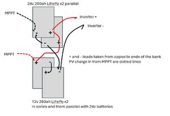
Have a bank which is now 2x 24v in parallel feeding 24v 3000 watt inverter.
Have 2x 12v 280ah batteries I want to add.
I know I may not be taking advantage of the full 280 ah but its what I have - same brand, BMS size, etc

So 2x 12v in series (hence 24v 280ah battery) in parallel with the existing 2x 24v batteries.
Its marine application so not used continuously and only used on the hook/mooring for 4-5 day trips.
At dock, PV and inverter are off and batteries are floated with a shore power charger.
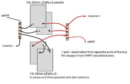
And do not really have room for + / - bus bars so did this as "best" way to just wire from terminals.

Plan to use best practice of having inverter leads at opposite ends of the bank (see sketch)

Does this also hold true for where the PV lines MPPT lines should be attached for balancing? I'm assuming so. Opposite ends of the bank and opposite the inverter?
Or can it also be the same as the inverter - which is better? Does it matter?

Thanks for the feedback.
 

Attachments

  • bankbank.jpg
    bankbank.jpg
    56.3 KB · Views: 6
You want to pull or push current into all the batteries at an even rate. This means all charge sources are split to opposite ends of the bus bars and the inverters are split as well.
 
Each battery?
+ Inverter lead goes to a 200AMP breaker (between the bank and inverter).
With the BMS(s) and reviewing other diagrams, I wasn't aware that I needed a fuse/breaker on each battery.

Since I Iack space with this set-up in a boat (BMS is 200AMP cont and 600AMP peak for 5 seconds)... can I use a 200AMP terminal fuse for safety.
Or for more margin, maybe use a 175AMP in the battery to battery locations?
At 24v for the inverter, this would be BMS protection as well and still allow surge from 3000 watt cont to 4,200 watts which I never hit.

In this scenario using terminal fuses and batteries in parallel, if one blows the bank is essentially disconnected correct?
 

Attachments

  • Screenshot 2024-07-16 101945.jpg
    Screenshot 2024-07-16 101945.jpg
    35.3 KB · Views: 0
Each battery?
+ Inverter lead goes to a 200AMP breaker (between the bank and inverter).
With the BMS(s) and reviewing other diagrams, I wasn't aware that I needed a fuse/breaker on each battery.

Since I Iack space with this set-up in a boat (BMS is 200AMP cont and 600AMP peak for 5 seconds)... can I use a 200AMP terminal fuse for safety.
Or for more margin, maybe use a 175AMP in the battery to battery locations?
At 24v for the inverter, this would be BMS protection as well and still allow surge from 3000 watt cont to 4,200 watts which I never hit.

In this scenario using terminal fuses and batteries in parallel, if one blows the bank is essentially disconnected correct?

MRBF fuse on each battery terminal - the breaker is good - just realize breakers respond slower than fuses - We generally recommend a class T fuse in an ignition safe mounting block. These should be rated for 25% above your BMS output. It depends on the vendor but for 100amps use 125amp fuse or 250amp fuse for 200amp output.

Like this - but be careful there are two versions - one for higher amp fuses and one for lower amp.

The inverter fuse should 150amps - 3000/24 = 156, so 150 - you could do 175 without a problem

You should use a bus bar for the output from the packs - and for series connected batteries look into an active equalizer - this will keep the two batteries balanced. You would need 2 of them since you have 2s2p configuration.

In all cases the wires should be up to the current you are pushing.

And use no-ox-id special on all the mating surfaces after cleaning them. It inhibits corrosion and it also makes for better contact.
 

diy solar

diy solar
Back
Top