diy solar

diy solar

Large spiky current draws with no additional load... ah crap

Those breadboards are not good for long-term use as they develop bad connections on the chips due to not being soldered or gold plated but are good for prototyping and proving it works. If you unplug the chips and just put them back in your problems may go away.
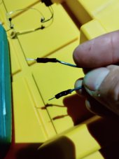
I think that is exactly what happened. Looks like the serial ground wire shorted. I replaced the bms and left the monitor off of it. When the new cells arrive and I build the 3rd battery ill build the monitor into an enclosure with soldered connections and test the bms here at the house.
 

Attachments

  • IMG_20211211_182458.jpg
    IMG_20211211_182458.jpg
    72.6 KB · Views: 10
Did you use the JBD's UART VCC line by any chance?
The VCC line is not standard voltage on the JBD, it outputs around 10v DC.
 
TTL errors, as suspected. First thing to look for when you see spurious data like this. I get similar.

I suggest the use of a galvanic isolater such as the ADUM range - I use them in my remote deployments. As well as helping protect your BMS, and helping to prevent ground loops - if placed in the middle of the TTL lines, they can help extend range and also act as a level shifter.

Cheers - M
 
Please also note that as others have alluded to above, in most cases it is NOT advisable to connect the positive side of the BMS serial port to your other devices. it carries non standard TTL voltages and may fry stuff, and in the majority of cases is not required unless you're trying to power stuff from the serial port, in which case you'll need to incorporate a voltage regulator to downconvert the voltage on the serial port to match your device, and also ensure your device doesnt draw more power than the serial port can supply, which isn't much. The other thing I'll mention is that, at least in my case, when I received a JBD bms from LLT, the wiring harness they had soldered up for the bluetooth dongle had the red wire and the black wire swapped - +ve was on the black wire, GND was on the red. Trap for young players.
 
Please also note that as others have alluded to above, in most cases it is NOT advisable to connect the positive side of the BMS serial port to your other devices. it carries non standard TTL voltages and may fry stuff, and in the majority of cases is not required unless you're trying to power stuff from the serial port, in which case you'll need to incorporate a voltage regulator to downconvert the voltage on the serial port to match your device, and also ensure your device doesnt draw more power than the serial port can supply, which isn't much. The other thing I'll mention is that, at least in my case, when I received a JBD bms from LLT, the wiring harness they had soldered up for the bluetooth dongle had the red wire and the black wire swapped - +ve was on the black wire, GND was on the red. Trap for young players.
good point about that pin

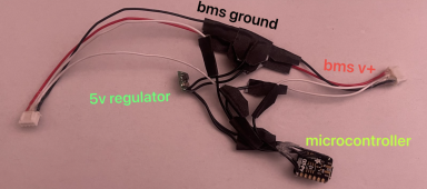
placed a 5V step down regulator between the BMS +ve voltage supply and the microcontroller to read the data from BMS, for a JBD experiment

this “pass through cable” allows me to connect the microcontroller to read BMS while also keeping it possible to suspend microcontroller serial communication and connect original bluetooth dongle to configure with mobile xiaoxiangbms app

the BMS must be sent a request for data in order to get data, so both transmit and receive are needed with JBD. so it’s important that the microcontroller not talk to BMS while using bluetooth adapter. to prevent crosstalk error

1639522249443.png
 
Judging from his fried ground wire it's absolutely possible - even probable - that he may have one of the 'reversed' +ve and gnd harnesses, or a ground loop. If this is the case he'll need to determine whether the dupont connector acted as 'the fuse' or whether it was something else that did. In my case that something else was the 3.3v regulator on the BMS.

Hopefully in this case lady luck prevails.
 
Back
Top