I keep getting a warning #13 which is a over voltage from pv? Each panel makes 39.8 volts and 375 watts. I have six panels i have 3 panels in series and 2 in parallel. Thats 238.8 volts for six panels divided by 2 should be 119.4 volts. How does it come up with 145 volts? What is max volts? Pv watts input is 2000 watts and does not reach over 1800 watts pv. I get a warning: 145 volts with a flashing #13. Can someone explain this to me ?


You are using an out of date browser. It may not display this or other websites correctly.
You should upgrade or use an alternative browser.
You should upgrade or use an alternative browser.
Mpp Solar 2.4k 24v
- Thread starter Chris
- Start date
gnubie
Solar Wizard
- Joined
- Sep 20, 2019
- Messages
- 3,844
Check the label on the back of the panels and post the VoC and Vmp figures. Also post the exact model of your MPP.
The MPP units have two voltages in the specs that matter for the PV input. The maximum rating beyond which thou shalt not pass and an MPPT operating range which if you exceed will result in the charger stopping charging but no harm to the unit will happen.
The MPP units have two voltages in the specs that matter for the PV input. The maximum rating beyond which thou shalt not pass and an MPPT operating range which if you exceed will result in the charger stopping charging but no harm to the unit will happen.

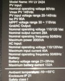
See that 41.7v open current voltage? Also note the mppt input is 115v... in winter, cold panels produce higher voltage, and you are getting closer to 41v than the mppt can accept.
Is there an easy way to limit the amount of input voltage from PV into control. Besides the obvious remove a panel ? Do they sell some kind of voltage regulator If 2000 watts or 145volts from pv is reached. I have not seen a Mpp Solar bigger then 2.4k using 120v/24v system. Is there a better controller without breaking-the bank? I liked the all in one controller.
For a safety margin I'd wire it based on VOC (47.6) and add the a factor of 1.25 for cold weather(if thats a factor for you) in other words 3 strings (serial) running in parallel should keep you in a safe voltage range.See that 41.7v open current voltage? Also note the mppt input is 115v... in winter, cold panels produce higher voltage, and you are getting closer to 41v than the mppt can accept.
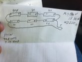
You currently have 2 strings (serial connected) of 3 panels that are joined in parallel. Instead wire them as 3 groups of 2 (in Serial ) that are then joined in parallel. Using the numbers in your photo that would make each strings voltage 79.6 Or a max of 99.5volts temperature corrected, (79.6*1.25=99.5) Which will be fine for the MPP. When you join those strings in parallel the voltage will stay the same but the amperage will multiply. 9.43x3= 28.29amps. However you need to use a multiplier to ensure you're accounting for heat(roof, conduit etc) and extended usage factors. Multiply 28.29*1.56 = 44amps Which is too much for 10ga PV wire. Watch this video
Therefore, instead of wiring all of the strings together into one PV wire you should join them in a combiner box and then size your breakers and PV output wire correctly to support the amperage
Therefore, instead of wiring all of the strings together into one PV wire you should join them in a combiner box and then size your breakers and PV output wire correctly to support the amperage
I should add that I'm just learning about this myself and have more questions than answers. I opted for higher voltage panels which drives additional design considerations not covered in Wills all in one videos and schematics. I also wanted to plan for expansion, so every component and design decision needs to be sized accordingly. There are also a number of safety (fuse/breaker/shutoff) considerations required for a truly safe design. Battery to Inverter, PV array to Inverter, Input AC to inverter and Surge protection from the array
SCClockDr
Solar Enthusiast
I concur with @Supervstech & @Mac6792, (47.6*3=142.8) offers NO appreciable margin. The MPPT's nominal input PV voltage is 80 & range is 30-115.
So I'd reconfigure to 2s3p or 3p2s 2 panels in series either configured in pairs or a pair of 3 paralleled panel strings.
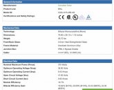
Voc = 95.2v
Isc = 19.8a
So I'd reconfigure to 2s3p or 3p2s 2 panels in series either configured in pairs or a pair of 3 paralleled panel strings.
Voc = 95.2v
Isc = 19.8a
SCClockDr
Solar Enthusiast
I put this together in Dia for illustration.

Very clever arrangement. I figured I was using 120 V so i thought i need to make 120v in configuration. I do see your point. At 95v won’t that limit the overall amount of available wattage ? Typically I only need or use about 9 to 10 AMPs at 1800 watts. Also i can not go over 2000 watts on pv input. That config will not increase wattage. That looks like it should be the fix for my problem. Thanks ScclockDr
Last edited:
Very clever arrangement. I figured I was using 120 V so i thought i need to make 120v in configuration. I do see your point. At 95v won’t that limit the overall amount of available wattage ? Typically I only need or use about 9 to 10 AMPs at 1800 watts. Thanks for your info. That looks like it should be the fix for my problem. Thanks ScclockDr
I don’t understand your question.
Solar output is 95v, wattage is what your panels can produce.
This 95v feeds the mppt, and it converts to your battery bank voltage, to get the maximum amps into the battery, or inverter.
The inverter converts the dc, to 115ish AC
I’m wondering if you might be able to help me understand what fuse is necessary between the MPP and the battery if you are using AGM’s. I have Lithium Iron Phosphate batteries coming but they are taking forever so I’ve purchased 2 cheap 35ah AGM batteries from harbor freight to run in series so I can get a little power at night to run the blower motor on my heater without having to run out in the cold and turn on my generator. I’m looking at the recommendations in the manual but I’m not exactly sure what to use still. Thanks!You currently have 2 strings (serial connected) of 3 panels that are joined in parallel. Instead wire them as 3 groups of 2 (in Serial ) that are then joined in parallel. Using the numbers in your photo that would make each strings voltage 79.6 Or a max of 99.5volts temperature corrected, (79.6*1.25=99.5) Which will be fine for the MPP. When you join those strings in parallel the voltage will stay the same but the amperage will multiply. 9.43x3= 28.29amps. However you need to use a multiplier to ensure you're accounting for heat(roof, conduit etc) and extended usage factors. Multiply 28.29*1.56 = 44amps Which is too much for 10ga PV wire. Watch this video
Therefore, instead of wiring all of the strings together into one PV wire you should join them in a combiner box and then size your breakers and PV output wire correctly to support the amperage
Attachments
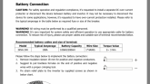
I’m wondering if you might be able to help me understand what fuse is necessary between the MPP and the battery if you are using AGM’s. I have Lithium Iron Phosphate batteries coming but they are taking forever so I’ve purchased 2 cheap 35ah AGM batteries from harbor freight to run in series so I can get a little power at night to run the blower motor on my heater without having to run out in the cold and turn on my generator. I’m looking at the recommendations in the manual but I’m not exactly sure what to use still. Thanks!
I've been using the info from the ALT-E store to guide my setup.
https://www.altestore.com/howto/recommended-inverter-cables-sizing-and-breakers-or-fuses-a62/.
Based on a 3kw inverter with 200 amp dc input from batteries they say to use a 300 amp fuse
Similar threads
- Replies
- 5
- Views
- 375
- Replies
- 6
- Views
- 205
- Replies
- 1
- Views
- 267
- Replies
- 20
- Views
- 822