


You are using an out of date browser. It may not display this or other websites correctly.
You should upgrade or use an alternative browser.
You should upgrade or use an alternative browser.
My first system
- Thread starter Budsy
- Start date
Budsy
New Member
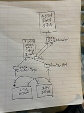
Sorry one addition is a on off switch after the Victron 175 A mega fuse.Hi this is a basic diagram of what will be my first build and would like anyone to tell me if there is anything I’m missing
Thanks
Budsy
New Member
Back up powerWhat is it used for?
Budsy
New Member
All little more info. All wires from batteries are 2 awg and the wire to panel is 10awgBack up power
Budsy
New Member
This may be a stupid question but on a 2 pole breaker is the input the bottom or the top?Back up power
Backup for what?Back up power
We need a lot more info about your planned usage if you want a decent answer.
Part of what you're asking is is this adequate for the intended use?
Budsy
New Member
It will be for powering my workshop day to day which is just lights and recharging power tools and computers and phones but also for backing up my fridge during power outagesBackup for what?
We need a lot more info about your planned usage if you want a decent answer.
Part of what you're asking is is this adequate for the intended use?
Budsy
New Member
My main concern is getting the fusing rightIt will be for powering my workshop day to day which is just lights and recharging power tools and computers and phones but also for backing up my fridge during power outages
add a fast acting fuse, immediately of the main positive. class t or similar. size this based on your max draw. including inefficiency's.
i would use thicker cables than your suggesting. dont cheap out on cable or lugs.
if your solar array is outputting 37amps be mindful mc4 connectors usually aren't rated for more than 30
i would use thicker cables than your suggesting. dont cheap out on cable or lugs.
if your solar array is outputting 37amps be mindful mc4 connectors usually aren't rated for more than 30
MisterSandals
Participation Medalist
3000W / 20V inverter cutoff / .85 efficiency = 176AMy main concern is getting the fusing right
A 175A fuse is on the edge of blowing at operating current. If you get a nuisance blow, try 200A.
Budsy
New Member
Should there be a fuse at each of the 24v batteries positive terminal?3000W / 20V inverter cutoff / .85 efficiency = 176A
A 175A fuse is on the edge of blowing at operating current. If you get a nuisance blow, try 200A.
Budsy
New Member
What sort of connectors would I use instead of mc4’s?add a fast acting fuse, immediately of the main positive. class t or similar. size this based on your max draw. including inefficiency's.
i would use thicker cables than your suggesting. dont cheap out on cable or lugs.
if your solar array is outputting 37amps be mindful mc4 connectors usually aren't rated for more than 30
Budsy
New Member
Sorry I had it wrong the panel is 13.7 short circuit current and 36.98 volts open circuitWhat sort of connectors would I use instead of mc4’s?
Not stupid. By convention line side of a breaker is the end the on/off lever points to when in shut position. In DC you do have to watch for polarized versions where it matters which lug is positive/negative wired.This may be a stupid question but on a 2 pole breaker is the input the bottom or the top?
MisterSandals
Participation Medalist
What is the battery chemistry? Lithium has a far greater ability to deliver a LOT of current so the more isolation, the better.Should there be a fuse at each of the 24v batteries positive terminal?
robbob2112
Doing more research, mosty harmless
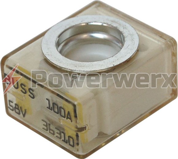
For fusing I would use a MRBF 200amp fuse on each battery and a 225 amp Class T in the middle of the cable to the inverter positive.
The MRBF keep the batteries from dumping into each other if one has an issue. The class T protects if there is a short inside the inverter.
#2 welding wire is rated at 208amps typically. But I would go up to 1/0 to cover issues like shorts - the increased mass and capacity gives time for the fuse to blow before the wire is red hot.
Watch out for knockoff fuses - Amazon is not a good source - here is a sample that is good.
 powerwerx.com
I am assuming you are using LiFePO4 batteries.
The MRBF keep the batteries from dumping into each other if one has an issue. The class T protects if there is a short inside the inverter.
#2 welding wire is rated at 208amps typically. But I would go up to 1/0 to cover issues like shorts - the increased mass and capacity gives time for the fuse to blow before the wire is red hot.
Watch out for knockoff fuses - Amazon is not a good source - here is a sample that is good.
EATON's Bussman CBBF/MRBF Battery Terminal Series Fuses 50A to 300A
Requires the use of terminal fuse blocks CBBF-MBC, BS5191, BS2151, BS5194 or BS5196. Provides high current protection in tight space locations. Ignition protected. 58V DC maximum voltage.
I am assuming you are using LiFePO4 batteries.
Budsy
New Member
Shut position meaning off?Not stupid. By convention line side of a breaker is the end the on/off lever points to when in shut position. In DC you do have to watch for polarized versions where it matters which lug is positive/negative wired.
Budsy
New Member
Thank you and yes life04For fusing I would use a MRBF 200amp fuse on each battery and a 225 amp Class T in the middle of the cable to the inverter positive.
The MRBF keep the batteries from dumping into each other if one has an issue. The class T protects if there is a short inside the inverter.
#2 welding wire is rated at 208amps typically. But I would go up to 1/0 to cover issues like shorts - the increased mass and capacity gives time for the fuse to blow before the wire is red hot.
Watch out for knockoff fuses - Amazon is not a good source - here is a sample that is good.
EATON's Bussman CBBF/MRBF Battery Terminal Series Fuses 50A to 300A
Requires the use of terminal fuse blocks CBBF-MBC, BS5191, BS2151, BS5194 or BS5196. Provides high current protection in tight space locations. Ignition protected. 58V DC maximum voltage.
I am assuming you are using LiFePO4 batteries.
robbob2112
Doing more research, mosty harmless
Shut position meaning off?
If the breaker is polerized it will be clearly marked on the side and usually on the terminals. In a standard build it is easy the panels are the positive (higher potential) and the top and the mppt is the negative (lower potential) and on the bottom.
Off is the bottom when you install breakers intended to work in the vertical position. Almost all breakers will work properly in either sideways or vertical but there are a few out there that are not only polerized but also have a specific position they have to be in.
No shut meaning breaker is turned on. Open is when breaker is turned off.Shut position meaning off?
I'm trying to find more info this, when I was researching for breakers for my current system I was reading something about a failsafe that melts and has to fall downwards as such the breaker must be placed vertical and the correct way up, but now I can't seem to find anything on the topic.Almost all breakers will work properly in either sideways or vertical but there are a few out there that are not only polerized but also have a specific position they have to be in.
Someone explained to me that positioning Vertical for a DC breaker was necessary due to the nature of arcs rising. The rising arc encounters a insulating baffle (arc chute) that breaks it. Hanging the breaker upside down would allow the arc to not rise into the arc chute.I'm trying to find more info this, when I was researching for breakers for my current system I was reading something about a failsafe that melts and has to fall downwards as such the breaker must be placed vertical and the correct way up, but now I can't seem to find anything on the topic.
However it was decades ago when I was taught the mechanics of breakers so my memory of particulars of design and theory is quite hazy now.
Similar threads
- Replies
- 3
- Views
- 329
- Replies
- 14
- Views
- 396
- Replies
- 5
- Views
- 237
- Replies
- 8
- Views
- 168