Rascal
New Member
- Joined
- Apr 11, 2020
- Messages
- 26
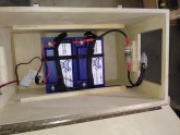
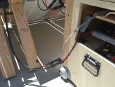
My fully portable DIY off-grid solar generator project is all but complete! I have a few i dotting and t crossing things to do but I tested it this afternoon and it's working! By the time I finished testing and got round to taking pictures it had completely topped off my battery bank and shut off the current from the array.
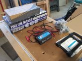
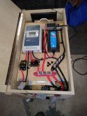
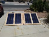
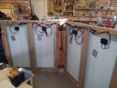
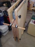
The battery bank is two Battle Born 100 amp/hour batteries wired in parallel for a combined 200 amp hours. The batteries and electronics fit into a chest I made for the purpose. I'm not happy yet with the wheels I put on the array assembly when it's folded up so I'll fuss with that. I'm going to try a Google Drive link vs. uploading pix in order to save space on the forum. If that doesn't work then I'll upload.
I'm stoked!
 drive.google.com
The battery bank is two Battle Born 100 amp/hour batteries wired in parallel for a combined 200 amp hours. The batteries and electronics fit into a chest I made for the purpose. I'm not happy yet with the wheels I put on the array assembly when it's folded up so I'll fuss with that. I'm going to try a Google Drive link vs. uploading pix in order to save space on the forum. If that doesn't work then I'll upload.
I'm stoked!
DIY_SolarGenerator - Google Drive
drive.google.com
")