diy solar

diy solar

Need help with 12v battery wiring.

relliott64

New Member
Joined
Feb 15, 2024
Messages
4
Location
PNW
Hello all. I have replaced my 2ea. 12v lead acid batteries with 3ea. 230ah lithium batteries wired in parallel. I am going to be relocating them just behind my 5th wheel RV's lower pass through, aft wall. There is not a ton of space back there due to all the existing plumbing so I am thinking about positioning the batteries as in the attached picture. Do they appear to be wired correctly so I'll get equal draw from each battery? If I did it this way, I'd need 2ea cables at 9.5" and 2 more at 19.5". Should I increase the length of the 2ea shorter cables so that all of them are the same length? I plan to eventually hook up a 2000w PSW inverter to the batteries for the few times a year where we may be camping without power. I'm just going to running a heavy cord from the 20amp outlet on the inverter the the 50amp plug on the rv with adapters. Thanks for any and all input.
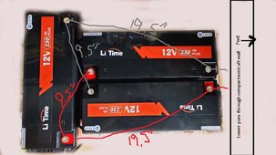
battery wiring1.jpg
 
That’s pretty clever! Yes, if they were all the same length you’d have better current balance. A 2KW inverter input current is going to approach 200 amps, you better be using wires as big as you can fit between the batteries, and then something larger to feed your inverter. Can you put the inverter with the batteries?
 
I was planning on 2/0 cabling between the batteries and the same to in inverter. I have a shunt/battery monitor for the negative run, and I will be utilizing a fuse and shut off switch for the positive side.
Those batteries have a 200amp BMS.
Should I be going with heavier cabling between the batteries and the inverter? And, what do you think about a fuse size before the inverter?
I'm looking at around 2' of cable (each way) between the battery and the inverter.
I've downloaded a bunch of wiring charts but would love to hear any thoughts for those here on the forum.
Thanks, Much.
 
Ive always wondered just how much difference it would make.

Im thinking with as many individual cells inside each battery the inequality could be more significant as the capacity increases.

If you care enough and have the means, you should use proper capacity bus bars with equal length cabling to avoid potential issues.

The parallel cable gauge sizing is relative to the highest power draw and/or distance from the inverter after the bus bar. Larger than required is better in most cases.

Also consider fusing the terminal of each battery (MRBF), and then a larger main fuse. T-class fuse is the preferred method for worst case scenario as they have a greater short circuit interrupt rating such as with your large capacity bank. And if one battery goes down for whatever reason, you still have power. Being able to isolate each cell has more upsides with this configuration than downside.
 
I do have 2ea. 300a bussbars that I could use. I could make all battery cables the same length that connect from the batteries to them. I'm thinking if If I go that way, would these work on each battery? https://www.amazon.com/dp/B0019ZBTV...otive&sp_csd=d2lkZ2V0TmFtZT1zcF9kZXRhaWw&th=1

Then, I would look at a 300a T-class fuse from the positive bussbar to the inverter.
In a scenario like this since each battery is wired independently to the bussbar, where does the battery cut off switch get installed? Do I need 3 cut off switches, one for each battery positive?
Same question for the shunt. 3 negative battery cables to connecting to the buss bar. how dies the shunt get installed?

And should 2/0 cables suffice for battery to battery, and if so then what size wiring to the inverter?
 
I do have 2ea. 300a bussbars that I could use. I could make all battery cables the same length that connect from the batteries to them. I'm thinking if If I go that way, would these work on each battery? https://www.amazon.com/dp/B0019ZBTV...otive&sp_csd=d2lkZ2V0TmFtZT1zcF9kZXRhaWw&th=1

Then, I would look at a 300a T-class fuse from the positive bussbar to the inverter.
In a scenario like this since each battery is wired independently to the bussbar, where does the battery cut off switch get installed? Do I need 3 cut off switches, one for each battery positive?
Same question for the shunt. 3 negative battery cables to connecting to the buss bar. how dies the shunt get installed?

And should 2/0 cables suffice for battery to battery, and if so then what size wiring to the inverter
yes stick to the name brand components such as Blue Sea.

only (1) main switch after the Tclass.
the shunt is first connection after the bank negative busbar.

optional is to insert a distribution block such as a Victron Lynx, or more bus bars for each pos/neg cable after the cutoff switch/after the shunt.

2/O is fine for parallel cables. a more scientific answer is provided by using a wire size calculator.

oversize cables are better for future expansion such as upsizing the inverter. i.e. your “2000W” inverter may not be a continuous rating and you require more capacity.

you should put together a schematic/diagram of your existing/proposed power system. it will help in any/every case.
 
MRBF fuses and holders on the battery posts, wire them with equal length to a busbar, after the busbar use a class T fuse holder and fuse. All of these are intended to protect the wires.

In all cases use a dab of no-ox-id on all contact points to prevent corosion... there are other anti corrosion greases but this formula cuts through the aluminum oxide on the terminals for low resistance.

The equal length applies to the cables positive battery to bus bar and cable negative battery to bus bar. The positive and negative do NOT have to match in length. Just the cables to the bus bars. So 16 inch positives to bus bars and 8 inch negatives to the bus bar is perfectly fine. The cables between bus bar and load do not need to be equal length. The idea with equal length is to keep the batteries balanced resistively with each other only.

So, 200amp MRBF fuses since each battery could put out that many amps. I would use 2 awg pure copper welding wire rated for 105c. For all battery wires. The class T I would make 200 amps as well since you do not expect to see more that 167 amps.

Now, were I you I would future proof and use bigger wires between the bus bar and the inverter. For that a 3000w inverter is 250amps so use 1/0 of the pure copper welding wire rated 105c. Then increase the class T to 300amps.

Note, if the inverter has a post connection put lugs on, otherwise you may need ferrules on the wire if they are simple screws touching the wires. If they are screws pushing a plate down then just plain wire is what you want.

Note - class T fuses and holders are a different size when you get 300amp and over.

And, there are many knockoffs on amazon. Those only fit the same brand holder. So also checkout newark electronics, mouser, and digikey websites and you can save even more most times.

Speaking of knockoffs, there are MANY bus bars listed on amazon and other places as 300amps, but the wouldn't carry half that. If you only paid $20 for the pair chances are you have cheap ones. To see for sure measure width and height in mm. Then take a file to a corner and get down to the base metal. If it is brass, L x W x 1.9 = rough capacity. If it is pure copper the 4.97 is the last multiplier.

Also, make sure to order a complete spare set of fuses in case one blows you aren't waiting on one to arrive.

3000 watts is the biggest practical size for 12v even though you can get up to a 5000w at 12v. Over 300amps the fuses get much more expensive and the wires get huge and hard to bend.

On the MRBF and class T fuses and holders, blue sea is great, but they take Eaton, littlefuse and busman fuses and holders and just put their name on the package. So search those brand names and you can usually save 20 to 50 percent.

And don't think to save a few bucks and skip the class T holder, the fuses won't take cable stress.

I would also make sure to have a boot on the ends of all cables along with shrink wrap that has glue inside it.

One final note, do not stack lugs if you can help it. If you must no more than 2 high. Highest current draw closest to the bus bar. And use the no-ox-id on all contact points. And use a torque screwdriver, 4nMon litime batteries.
 
i sincerely appreciate all the info you guys have given.
Since, I last posted, I have changed my mind from a 2000w inverter, to a 3000 Victron Multiplus ii 2 x 120.
Please critique my plans below.

I have 3ea. Li time 230 ah batteries to be wired in parallel. (200amp BMS in each battery)
I will be installing 200amp MBRF fuses on each positive battery post.
I will be wiring from the MBRF fuses directly to buss bars. I already have these ones..will they be okay? https://www.amazon.com/Batteries-Suitable-Automotive-Applications-Electrical/dp/B0C6K78QT2?th=1
Due to the higher wattage inverter I'm going to use, what size cables should I use from the batteries to batteries and batteries to the buss bars and from the bussbars to the inverter? (I think that victron specifies 2 separate 1/0 pos. and neg. cables to the inverter)
What size t-class fuse between the positive bussbar and the victron inverter? ( I think victron specifies 400a)
I also have a 275a disconnect switch which I'm not sure will be sufficient with my new plan. I believe that this should installed between the t-class fuse and the inverter? https://www.litime.com/products/litime-12-48v-battery-disconnect-switch

Last and probably dumbest question...Since I'll be removing my existing converter/charger, should I just wire from the positive bussbar to the distribution panel to get power my 12v loads?
Thanks for helping out a newbie.
 
Back
Top