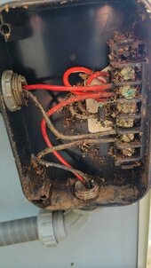
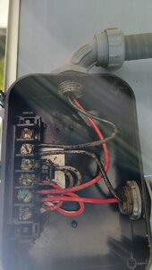
I have two 25 year old 12V Solarex VLX-32 32 watt panels hooked in parallel that operate a gate. Our old gate was 12V and the new gate is 24V. I'm told it would be better if the panels were connected in series. I opened the lower panel junction box and it was full of ant crud and the connectors are badly corroded. I also see an anode and some jumper wires. I could cut some wires, use wire nuts as connectors and change it to in series. Would that work? Is the anode important? Do I have to buy new panels? Currently, they're generating 17V, which seems OK, and the gate works on sunny days, but there's four houses behind the gate and the two new 12V 7AH batteries aren't keeping up on a cloudy day. Thanks for your help!


You are using an out of date browser. It may not display this or other websites correctly.
You should upgrade or use an alternative browser.
You should upgrade or use an alternative browser.
Old solar panel has corroded junction box
- Thread starter jimcrist
- Start date
yodamota
Solar Enthusiast
really to me that looks more like dirt/ant shite. What about looking at it after cleaning it up?
Andrewr05
[Replicant 42069]
Get a nylon brush and some electrical contact cleaner.
This. Plus one of those computer dusters to loosen it prior to cleaning.Get a nylon brush and some electrical contact cleaner.

The Diode is likely just short protection to auto-blow a fuse if it's wired wrong.
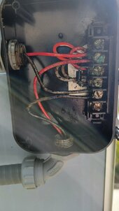
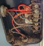
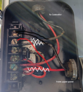
I cleaned it some more using a toothbrush and terminal cleaner. The positive terminals are quite corroded. The negative terminals are OK. The junction box on the upper panel is in good shape, since it never got ants. I think I can leave the terminals alone and just cut three wires and change it from parallel to series with two wire nuts. The second photo is an attempt at my plan. The yellow lines are cuts and the blue line represents the new connections. Any input would be appreciated...thanks!
Attachments
400bird
Solar Wizard
I don't think that's exactly right to put them in series, but I can't tell what is the pos/neg output from the panel that junction box is mounted to.
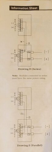
I came back to check this before I snipped wires. Yikes...thanks...I think you're right. I found this in the info sheet that came with the panels. The documentation is upside down from the way the panels are mounted so I reposted the junction box upside down. I guess the new plan is shown below. Any help would be appreciated...thx...
Attachments

Last edited:
400bird
Solar Wizard
I'm still not sure what they have going on the other side of the terminal block, but you're drawing looks like exactly what they recommend.
Do you have a charge controller between the panels and battery?
Do you have a charge controller between the panels and battery?
yodamota
Solar Enthusiast
can the charge controller handle the series connection? I assume it will operate around 44VOC and around 34VMP. Being this is a small charge controller it might only be a PWM... I am sure you checked this...I guess you saved me from a real mess. Thanks much for speaking up. I'll try it tomorrow. Yes, there's a charge controller built into the board that operates the gate. It'll handle up to 80W.
Just noticed one of these conduits is missing the nut. Probably how the insects got in.
Thanks for noticing. The connector for that red wire is too corroded to remove, so I used caulk in lieu of a nut. Great news! The switch from parallel to serial was a success and the gate still works. Hopefully, the batteries will appreciate the switch. Thanks everyone...great forum!!
Similar threads
- Replies
- 5
- Views
- 631
- Replies
- 4
- Views
- 504
- Replies
- 21
- Views
- 884