You are using an out of date browser. It may not display this or other websites correctly.
You should upgrade or use an alternative browser.
You should upgrade or use an alternative browser.
Panel shows voltage on its own but 0 in series.
- Thread starter diWhy
- Start date
robbob2112
Doing more research, mosty harmless
So, your negative lead on the end of the diodes with the line and it should read some reasonably small value - then swap and put the positive lead there and the negative lead on the other end and it should read infinity
If you get a short in both directions you have a bad diode - because they are in parallel you would have to snip one or both loose to find the bad one.
This is with the panels face down or covered.
If you get a short in both directions you have a bad diode - because they are in parallel you would have to snip one or both loose to find the bad one.
This is with the panels face down or covered.
When I tested, the panel was not covered but every diode in both directions were solid short. Meaning, instead of any ohms reading, I was getting a beeping sound like when testing connectivity. I'll have to do it again this time covered with a towel or something heavy because it was an awkward position so I feel like I didn't do it right.
robbob2112
Doing more research, mosty harmless
With the panel covered or face down if you get a dead short in both directions you have at least one bad diode in each set.
The thing that is confusing is you read any voltage across it when not connected, if all diodes are failed short you should never get any voltage out of it.
Most meters if they have a continuity beep also do diode test - Is there maybe that symbol there on the meter face and you missed it?
Diode test will be a single beep if good
Yes, the meter has continuity/resistance test and that's the setting I had it on. In fact, I tried two meters just to be sure since it's hard to reach.
All diodes, no matter the polarity resulted in a beep. I think one of then showed a small resistance.
All diodes, no matter the polarity resulted in a beep. I think one of then showed a small resistance.
Last edited:
robbob2112
Doing more research, mosty harmless
A beep or a constant tone?
A beep means the diode is good - a constant tone means it is bad.
A beep means the diode is good - a constant tone means it is bad.
Then to me that sounds like a faulty MC4 connection or the polarity is cancelling out the voltage.>Can you clarify that this is still all open circuit testing - as you put in post #3?
No load, nothing is connected to the inverter yet so only the panels and the strings are being tested.
>are you saying that a voltmeter connected to the dodgy panel reads a voltage on its own, but as soon as you connect it to
>other panels, despite those other panels not being connected to anything else, it shows no voltage?
Correct. If I test the panel on its own, it shows good voltage. As soon as I connect it to another panel, in a string of two, there is no more voltage across the two panels.
>Also, regarding the connecting in series.... does this strange behaviour also happen if the panel-in-question is at one end of the open
>string, in the middle AND at the other end of the string?
Correct. this is how we confirmed this panel is not working right. I tried connecting another panel on its negative and get nothing. I tried connecting to on its positive, I get nothing. As soon as another panel is connected, there is no more voltage flow.
>Are the panels just raw panels, or do you have any optimisers or similar attached to them.
Nothing, just the panel/s.
If there is no load/current flow then the bypass diodes are not operating any more than the panel on its own.
What is the voltage of the panel-in-question when one side is physically connected to another panel?
Recovering EE
Solar Enthusiast
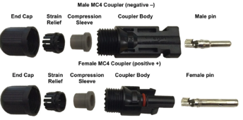
I am guessing it has MC4 connectors. Did you check to ensure that it is not wired in reverse polarity? Your meter should show if the panel when measured by itself is giving you a positive or negative voltage. Standard is the male MC4 is positive and the Female MC4 is negative.
Every PV panel I've worked with, has the + on the female connector, and - on the male connector, with the naming convention coming from the metal pin configuration, rather than the coupler body appearance.

What is the voltage of the panel-in-question when one side is physically connected to another panel?
Recovering EE
Solar Enthusiast
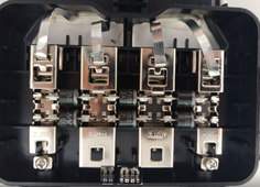
Is it possible that one or more of the bypass or blocking diodes is installed backwards?
I guess it's possible since it was never used in a string before, it used to have a micro inverter on it.Is it possible that one or more of the bypass or blocking diodes is installed backwards?
robbob2112
Doing more research, mosty harmless
That picture looks correct where it shows all of the diodes.... the positive end of the string to the left and the negative to the right.... Which means the negative wire should be hooked up on the left and the positive wire on the right. Normal operation positive wire is higher potential so the diodes are cut off.... If there is shade or something preventing voltage from being generated the potential from the two panels on either side cause the current to flow across the diodes with a bit of lost voltage per set. You have 2 in each set to handle the current, I would assume they are 10amp diodes or so just from the look without the number on them.
robbob2112
Doing more research, mosty harmless
You can also try hooking the panel in without diodes and it should work fine, but any shade will kill all production. Might be a good test.
Buy new ones and swap them - I could read enough of the number to find the part
robbob2112
Doing more research, mosty harmless
When I say buy new ones, I mean the diodes
No problem, I'd like to accomplish both. If I could fix the two that aren't working, that would be a bonus.When I say buy new ones, I mean the diodes
new off grid
New Member
- Joined
- Jan 27, 2020
- Messages
- 133
did you check to confirm every single panel was good ?I'm making up 7 panel stings. I've come across one that's doing something I'm totally baffled about.
I can measure voltage when it's not connected to anything but if I connect it in series with just one other panel, then it outputs zero voltage.
All I can think of is there is something in the small black box the cables are coming from that disables the output when the voltage goes higher than the panel can output on its own?
Stumped.
the the only reason there's no voltage after you connect in serial is
at least 1 of the connector is bad, when 1 bad, the whole string is zero voltage
now, check one by one connector , you will find out which one soon
good luck
not worth checking if both are outputting voltage on their own it just means the connector isn't working there's really no other reason it can be.I've seen the little diode box open on some videos but is it even worth trying to fix if that's the problem?
You already checked polarity and others are having you do it more but it can't be that if the multimeter isn't faulty
anyway take a wire and stick it into the MC4 connector of both of the units and stick them together and then see if it works
Sorry, I'm not really following here. I checked every single panel and every single extension I made. I had to make a bunch of 2' extension cables.not worth checking if both are outputting voltage on their own it just means the connector isn't working there's really no other reason it can be.
You already checked polarity and others are having you do it more but it can't be that if the multimeter isn't faulty
anyway take a wire and stick it into the MC4 connector of both of the units and stick them together and then see if it works
I found nothing wrong with any of the extension cables and the string works, only not with this panel connected. Once this panel is connected on either end of the string, the string shows no voltage, completely open circuit.
yea so the MC4 connectors are not connectingSorry, I'm not really following here. I checked every single panel and every single extension I made. I had to make a bunch of 2' extension cables.
I found nothing wrong with any of the extension cables and the string works, only not with this panel connected. Once this panel is connected on either end of the string, the string shows no voltage, completely open circuit.
stick a wire into the MC4 connector

stick the other end of the wire into the other MC4 connector of the other solar panel
this ensures the connectors are now connecting
Similar threads
- Replies
- 3
- Views
- 135
- Replies
- 1
- Views
- 189
- Replies
- 12
- Views
- 391
- Replies
- 7
- Views
- 138
- Replies
- 16
- Views
- 724


