BigCharlie
New Member
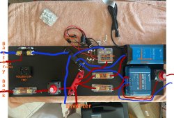
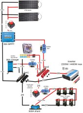
Hi y'all. What you do think? I'm planning on mounting it today. The batteries I'll top-off individually before powering up.
Also, it just occurred to me that I haven't considered grounding.
The bus bars are 4 post, I have 5 connections. I'm planning on putting the battery and inverter on the same post.
The batteries are connected in a diagonal fashion. I'm considering attaching them individually to a post at a later date.
More details after images.


6 12V 105Ah lead-acid,
Victron Blue Smart IP22 Charger 12-Volt 30 amp 120V,
GIANDEL 2200W Pure Sine Wave Power Inverter,
Victron 500A SmartShunt,
Victron SmartSolar MPPT 100V 30 amp 12/24-Volt Solar Charge Controller,
Renogy Flexible Solar Panel 175 Watt 12 Volt
Cut-off switches are rated at 275 A continuous at DC 12V, 455 A intermittent at DC 12V, 1250 A momentary at DC 12V
Bus bars rated at 250 amps @ 12V

 diysolarforum.com
Is this kosher?
This is to power my computers on a day-to-day basis (50W-150W 120V x 5-8 hours) with a little extra storage for blackouts. I didn't design it off of 'need requirements' but off of 'what I can do in the space available.' I don't have the panel space to power the entire apartment. I realize the components are outsized for this application I'll reuse them in a future project.
Panels get equal sun.
First off, I don't know what to think about the shore charger. I'm thinking it might need to be connected directly to the batteries, same posts as the 2/0 going to the buses. I'll have the charger top-off the batteries overnight.
I don't plan on there being any draw off of the inverter overnight. If there is (say 100W), would there be an issue with the charger and inverter running at the same time?
Also, it just occurred to me that I haven't considered grounding.
The bus bars are 4 post, I have 5 connections. I'm planning on putting the battery and inverter on the same post.
The batteries are connected in a diagonal fashion. I'm considering attaching them individually to a post at a later date.
More details after images.


6 12V 105Ah lead-acid,
Victron Blue Smart IP22 Charger 12-Volt 30 amp 120V,
GIANDEL 2200W Pure Sine Wave Power Inverter,
Victron 500A SmartShunt,
Victron SmartSolar MPPT 100V 30 amp 12/24-Volt Solar Charge Controller,
Renogy Flexible Solar Panel 175 Watt 12 Volt
Cut-off switches are rated at 275 A continuous at DC 12V, 455 A intermittent at DC 12V, 1250 A momentary at DC 12V
Bus bars rated at 250 amps @ 12V
Copied from my first post at:

My first setup. Is it wired correctly? Is perfectly balanced charging real?
EDIT: I forgot to add that I'll have a battery isolator switch between the panels and controller. And thinking about putting another one between the battery fuse OCPD1 and the bank. Is this kosher? This is to power my computers on a day-to-day basis (50W-150W 120V x 5-8 hours) with a little...
This is to power my computers on a day-to-day basis (50W-150W 120V x 5-8 hours) with a little extra storage for blackouts. I didn't design it off of 'need requirements' but off of 'what I can do in the space available.' I don't have the panel space to power the entire apartment. I realize the components are outsized for this application I'll reuse them in a future project.
Panels get equal sun.
First off, I don't know what to think about the shore charger. I'm thinking it might need to be connected directly to the batteries, same posts as the 2/0 going to the buses. I'll have the charger top-off the batteries overnight.
I don't plan on there being any draw off of the inverter overnight. If there is (say 100W), would there be an issue with the charger and inverter running at the same time?
Last edited:


