farmhand
Solar Enthusiast
- Joined
- Aug 26, 2022
- Messages
- 232
Good day all, hope to get some replies here:
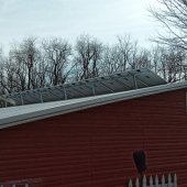
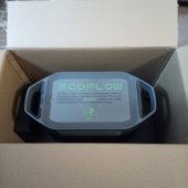
My panels on the chicken coop are 120' from the Ecoflow Max 2k.
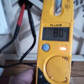
The Eco MPPT pulls in 800w.
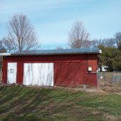
My 24 100w panels are in (6) strings of (4) panels.
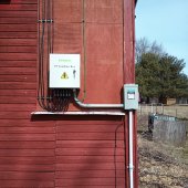
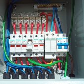
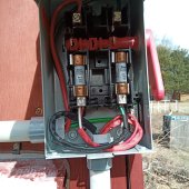
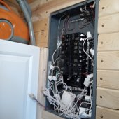
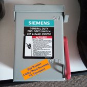
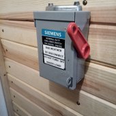
All strings fused, dioded, surged, 15A DIN breaker - then to a Siemens fused disconnect with 15a FRS fuses. Then>>>
First leg 50ft: (From coop to outhouse) is (4) #12THHN.
Second leg 60ft: (From outhouse to cabin utility room) 12/2RX
By all calculations, and using several different sites, I feel the 7-8 amp draw from the ECO will be no issue for heat on the line. Yet not being to much in-the-know on residential DC.... do you agree this wire size for the distance is safe with DC?
Thanks all, I don't post much but stock the forum often & enjoy the threads on here")
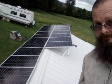
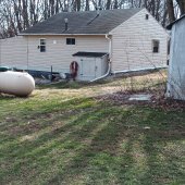
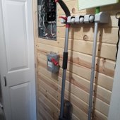
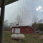
Here's a pic during the build last summer*
My panels on the chicken coop are 120' from the Ecoflow Max 2k.
The Eco MPPT pulls in 800w.
My 24 100w panels are in (6) strings of (4) panels.
All strings fused, dioded, surged, 15A DIN breaker - then to a Siemens fused disconnect with 15a FRS fuses. Then>>>
First leg 50ft: (From coop to outhouse) is (4) #12THHN.
Second leg 60ft: (From outhouse to cabin utility room) 12/2RX
By all calculations, and using several different sites, I feel the 7-8 amp draw from the ECO will be no issue for heat on the line. Yet not being to much in-the-know on residential DC.... do you agree this wire size for the distance is safe with DC?
Thanks all, I don't post much but stock the forum often & enjoy the threads on here
Here's a pic during the build last summer*