diy solar

diy solar

QS 1 Microinverters not as advertised...or am I doing something wrong

patdown45

New Member
Joined
May 20, 2020
Messages
18
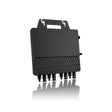
I am in the process of building my own 7.2kw grid tied system using TRINA 180w Da01 modules I have 46 and have started a small array using 8 in pairs of 2 in parallel to each of the 4 channels on my QS1 and have seen quite large disparities between the 4 channels even though all the modules are in direct sun without shading. channel 2 is always showing 2 watts which means no output, but when I check at the back of the panel as I can pull off the junction box cover and check the voltage and the amperage output at each pair as they are wired they are all putting out between 9 and 10 amps. is this overloading the QS1? Also I had one pair tied in using a set of short cables designed to parallel 2 into one and found that it was not allowing the amperage of both modules to be delivered? I replaced the cable with the solid one piece two to one connector and now all pairs are putting out the correct amount of power...but the ECU app is showing channel 2 is not and the other 3 are miss matched in the amount of power output? I am glad I did this test before I purchase another 3 microinverters as I believe there is some issues with these QS1 Micro inverters but now I have over a grand tied into these 3 and the trunk cableIMG_20200627_163215_01.jpgIMG_20200627_163215_03.jpgIMG_20200627_163215_02.jpg20200704_093650.jpg20200703_170622.jpg20200703_170618.jpg20200703_170614.jpg This pole mounted set took too much time and I will be ground mounting the rest a single long ground mount array that is 5 modules in landscape high and 8 rows wide. As my local town is asking 10 dollars for the permit fee PER MODULE before any of the other permit fees, I am building a "Portable Mounted Solar array that be plugging in and unplugged as well as the pipes will be able to be unbolted from the pipes that are cemented into the ground like the one from a local solar array nearby in the photo you can see they have mechanical fasteners bolting the array piping to slightly larger pipes that are buried. I am hoping I can get this thru an inspection. The Power company is not having any problem with the documentation I provided on the modules and the QS 1 micro inverters by AP systems and have tentatively approved me for a 7.2KW system which was the original plan to use 6 of the QS1 microinverters and tie 8 modules of 180 watt each in pairs (360 watt) max amperage 10 amps to each of the 4 channels in two strings of 3 QS 1s each string will go to 20 amp 240 volt double pole breaker in the garage. I am hoping they don't insist on a gfci or arc fault breaker on this system because it will not be able to back feed thru one of those breakers. My biggest concern now is finding out AP systems will not help with Do it yourself installations I went with their system because of the simplicity of not having to have so many parts as now with solar edge in addition to the central inverter you also have to get each module a power optimizer which adds so much more cost. I found these modules from a craigs listing that was from a auction purchase on several pallets of TRINA 180W DA01 modules. They are new and have no damage. The only problem is all the connectors are not MC4 they are a different sytle that is not in use called TYCO connectors. I have been swapping them out for MC 4 and will have to make up several longer extensions to rech all of the 8 modules to each of the QS1s. My biggest concern if they cannot handle the 360 watts and 10 amps each Chanel I will have to redesign everything. the photo of the raking system I planned on using is below I am using the Iron ridge system for the rails and the mounting except for the top caps which are $35 each and I am making for about $10 because I need 16 so instead of $560 I will spend under $160 the side rails also are $12 each from Iron Ridge for an Item that I can produce for $6 and for the required 32 I will spend $192 instead of the $384. I am buying all the bonding fasteners these 2 photos are not my system but what I am hoping to build. I just found out due to covid 19 the local adj will not be coming out and I just have to sign a document that everything is to code! Any advice on the Microinverters will be greatly appreciated.0609201538.jpg
0618202027.jpg
 
here is a screen shot of the dead channel it is in a pdf format
 

Attachments

  • intoViewOptModule.pdf
    64.7 KB · Views: 9
Did a quick check in the garage with a load applied that was drawing 30 amps (charging up the Honda Clarity) when I checked the load coming and going from the main panel (this is a sub panel) the draw was only 22 amps so the 7 to 8 amps was being delivered to the Car directly by the Solar panels. Strangely when I tested the individual leads L-1 and L-2 of the 20 amp breaker they only showed 1 amp?? can anyone explain why I shut off the solar panel breaker to confirm that was the case as the second I did the draw from the main now jumped up to what the car was drawing 30 amps. I see now it is most likely a software glitch with AP systems monitoring and I could care less as there is many other monitoring systems out there...However I am NOT just going to believe the one the power says is on there system with there so called "Smart meters" I am looking at the whole house system like the "Sence" and they make a solar additional line to add but my main and sub are more than 80' apart so I will just have to get 2 systems unless there is another way
 
I'm very confused. So let's break this down a bit. Here's what I'm understanding, please stop me and correct me if this isn't accurate.

You are operating in a grid-tied environment.

You have your ground mount solar panels on one rack, and your tracking system on another rack. We are focusing on an issue with the tracking rack system.

You are using TRINA 180w Da01 panels that have the following specs:

1594226517808.png

On your tracking rack, you have 8 panels in pairs of 2 in parallel. Each set of 2 parallel panels connect on to a channel on your QS1.

So for each parallel string you have 360 watts peak, 36.8 volts at Vmp and 4.9 amps at Imp. You have 44.2 volts open circuit and 10.7 amps short circuit, per parallel string.

3 out of a total of 4 channels are working perfectly fine, and your data logging software is properly showing the output. Channel #2 however is not showing output in the software but you have power going into the micro inverter.

In theory, if all 8 panels were working in the best scenario, you have 1440 watts. You are backfeeding this into a panel in your garage. In your garage you have a load, in this case it is an electric car.

This load is drawing 7200 watts (30 amps x 240 volts). You are feeding 1400 watts (around 6 amps) into the panel from solar, so the remaining 5800 watts (24 amps) are coming from the utility. This makes it sound to me like the solar system is operating properly. If the panels are rated to generate 1400 watts (180 watts * 8 panels) and you are saying that in actuality you metered around 8 amps coming from your grid-tied panels, I would suspect all channels are working.

This should be an accurate specsheet / listing of your QS1 microinverter.

Does this sound about right?

If we can get some basic facts clear, then we can better understand what acutally is going on.
 
Last edited:
You have a correct understanding of my system with the exception that it has no Auto tracking I can however manually tilt intern the pole mounted installation it was a lot of work to manufacture this from scraps and bits and pieces I'm building the rest of the system on the iron Bridge racking ground-mounted designs using schedule 40 piping and there racking rails with their mounts however I'm making my own caps and L brackets as they want way too much money for theirs as far as my panels producing I'm convinced they're producing the only thing that has me a bit confused when I measure the amps at the breaker where they're producing it was hardly showing anything which is in contradiction with what I saw on my meter from the top of the panel as it was drawing less when the system was on and when I turned off the solar system the amp reading went right up to 32 so what I don't understand why I didn't see those 6 amps from microinverter circuit with my amp meter only at the main feed to the panel was I able to see it


I'm going to invest in a higher quality meter that can do inductive amp readings on DC so I can get a more accurate reading on what my panels are producing as well as what the inverter is producing the software is definitely Jack though right now it is showing Channel 2 as putting out nothing the other three channels should be very similar as there's no shading on any of these panels however it is showing two channels fairly close to each other and a third channel is way out in left field as far as the numbers and none of the numbers even come close to what it should be as far as Watts
 
Have you checked all your connections that they are crimped correctly and not crimped on insulation. Also that the polarity is correct off the panels. If is hard to follow what you are saying. Maybe breakup your paragraphs and talk about one problem at a time if you have more then one problem.

I have 4 QS1's in a similar portable configuration and had no issues. The only thing I don't like on the QS1 is that when my invertor frequency shifts to power back the QS1's, the QS1 microinverter just shuts off for 5 minutes. The QS1's don't feather back like I am told the Enphase Micros do.

Good Luck
 
Last edited:
I don,t believe there is an actual problem with the equipment as when I tested with an amp meter the output is good. I believe the software from AP systems is not correct as it is not displaying the correct power output, at the panel level as it should.

However when I checked the power going in and out of my power panel with a load going ( charging the car draws 32 amps) the power draw at the top of the box (those are the feed wires going back to the house and the grid) those wires showed 24 amps.

The 8 amp discrepancy is what my panels were producing and delivering to the shortest path which was the car charger.

As soon as I turned off the solar panels the power feed cable load went back up to 32 amps
 
I don't use those software programs. I have an app that shows total power draw from my smart meter and that is all I see.

Is the QS1 software free?

Can you move the 2 suspect panels that are reading funny to another channel?
 
Special thanks to HighTechLab for the summary and h/w links!

System: 8 x 180W panels (1440W) with 2 in parallel to each of 4 MPPT inputs (360W per mppt, 36.8V, 9.8 amps) on a 1200W microinverter.

Problem: 3 of the 4 mppt inputs are "working". #2 only shows 2W, but the back of the panels shows it is outputting 9 to 10 amps.

Mystery!
How can the output be two watts when then input is 360 watts? If the SCC is blocking power on #2, there should have been 0 amps measured.
Did you use a clamp meter to measure the 9 to 10 amps? If not, how did you get that reading?

Troubleshooting
Despite the "full sun", it's doubtful the panels are producing the full 180 watts, so you're probably not exceeding the 1200 watt capability of the microinverter. Most likely (as @ghostwriter66 would be quick to say ;-) it's the cable or one of the connectors. Could also be the microinverter.

Stuff to try first
Try swapping the cables between MPPT inputs #2 and #3. If the problem shifts to #3, a bad cable.
If it doesn't then it could still be one of the connectors or the microinverter.

Possible Weird Explanation
One possible explanation for the mystery is that the 2nd MPPT is actually working, it's just reporting the wrong output.
You can test this by measuring the volts and amps on each of the MPPT inputs and the amps and volts on the output microinverter output.

If the output watts plus the inverter efficiency is the sum of the input watts, then it's the microinverter's reporting feature on input #2 that's busted. You can verify that by swapping the microinverter (do it early in the day or when it's cloudy if you're worried about exceeding the 1200W power level) to see if all four MPPT inputs provide valid data.

Please keep us in the loop as to what you find!

Update
...I don't believe there is an actual problem with the equipment as when I tested with an amp meter the output is good....
That'll teach me to post before reading everything! So, you're seeing the correct AC output power and think it's a software bug? Seems like it would be a glaring bug... if so they probably have an update.
 
Last edited:
Yes I am going to buy a clamp meter that can read DC as the one I have cannot but the way I read the output on the panels was to pull off the junction box cover and using the meter on DC amps with the probes I stabbed them in on the pos and neg of the module at the junction box to read the close to 10 amps on each pair of 180 watt modules that are in parrallel so I know the wire between them is good....but the final connector at the microinverter could be suspect so I swapped the wires bvetween channels and the monitering software always only shows channel 2 as 2 watts or no output? input? their documentation (built in China) is crap so to see in real world checking at the subpanel where the wires come in from the array to a 20 amp 220volt circuit I can check the power flow in A/C amps to see what is getting back fed that wire is showing almost nothing on either leg L-1 or L-2 However when I check at the main feed from the house to the sub panel I was able to see a significant difference when I had a load drawing right there as the car charger was drawing 30 amps and when I looked at the draw drom the house was only 24amps I will check again in a few minutes but I think I can see what the program is displaying;

it is saying right now I am producing 271 W.....well why not the 800 to 1100 that the panels should be producing?

we know that Amps is watts divided by volts

271 watts at 240 volts is only 1.129 amps which corresponds to what I was reading at the wire coming from the panels


Now I am truly puzzled and will reduplicate the test from yesterday I must have misread my amp meter as there is no way those 8 panels would be producing that much power even at best.

Also I have 2 more brand new microinverters that I can just plug in to test and see if they are doing the same thing....I am started to suspect I have a bad microinverter....but as always more testing to follow....
 
It's very easy for us readers to get confused with a written explanation.... a diagram that shows the components and what the volts/amps are at spots they were measured would really help to clarify things. My guess from #10 is you've a bad assumption somewhere, it would probably be clear where/how with a diagram.

Thanks for keeping us updated! I always learn a lot following along these troubleshooting threads.
 
Yes I am going to buy a clamp meter that can read DC as the one I have cannot but the way I read the output on the panels was to pull off the junction box cover and using the meter on DC amps with the probes I stabbed them in on the pos and neg of the module at the junction box to read the close to 10 amps on each pair of 180 watt modules that are in parrallel so I know the wire between them is good
Do I understand right that you are using your meter between the outputs of the panels? This essentially is causing a short circuit if you aren't using a clamp meter. Measuring amps is done by putting the meter in series with the supply and load - simply shorting out the panels with the meter is dangerous.
that wire is showing almost nothing on either leg L-1 or L-2 However when I check at the main feed from the house to the sub panel I was able to see a significant difference
Are you using a clamp meter here to measure this??
it is saying right now I am producing 271 W.....well why not the 800 to 1100 that the panels should be producing?
Are the panels in 100 full direct sun? The panel output is dependent on the intensity of sun hitting them as well as the angle. Is it possibly the sun at this time is not optimal??
 
Thanks for the advise on how to not blow the fuse in my meter I was checking the amperage wrong. I will wait until I get the correct clamp meter for DC. However I was able to determine that that microinverter is bad I swapped out that Michael inverter for another and it is reading evenly across all channels so I'll have to return that one I'm testing the other two and using the app from AP systems to monitor how much power it's getting I was also able to monitor at my sub panel in the garage with a load and a solar going at the same time I could determine it was actually only putting out about 3 amps difference between the load of say my compressor running and the load coming from the house or going to the house that 3 amps was being made up by the solar energy which is disappointing as 8 modules the can produce 180 Watts was all together even on a not very bright day producing only 3 amps at 240 volts ac that equates to 720 Watts which was what was being indicated by the AP software I'm hoping I'll have an actual sunny day to do a real test soon
 
I found a bad panel in the group of 8 as I blew one of the diodes by doing the amp reading incorrectly by shorting it out. I replaced the diode and all panels are putting out max amperage as I am checking now with an inductive dc amp meter. Now onto the next 40 modules..I have 15 on the rack and just need to replace all the tyco connectors with MC4 connectors and we can triple our power production
 
Thanks for the advise on how to not blow the fuse in my meter I was checking the amperage wrong. I will wait until I get the correct clamp meter for DC. However I was able to determine that that microinverter is bad I swapped out that Michael inverter for another and it is reading evenly across all channels so I'll have to return that one I'm testing the other two and using the app from AP systems to monitor how much power it's getting I was also able to monitor at my sub panel in the garage with a load and a solar going at the same time I could determine it was actually only putting out about 3 amps difference between the load of say my compressor running and the load coming from the house or going to the house that 3 amps was being made up by the solar energy which is disappointing as 8 modules the can produce 180 Watts was all together even on a not very bright day producing only 3 amps at 240 volts ac that equates to 720 Watts which was what was being indicated by the AP software I'm hoping I'll have an actual sunny day to do a real test soon
 
Special thanks to HighTechLab for the summary and h/w links!

System: 8 x 180W panels (1440W) with 2 in parallel to each of 4 MPPT inputs (360W per mppt, 36.8V, 9.8 amps) on a 1200W microinverter.

Problem: 3 of the 4 mppt inputs are "working". #2 only shows 2W, but the back of the panels shows it is outputting 9 to 10 amps.

Mystery!
How can the output be two watts when then input is 360 watts? If the SCC is blocking power on #2, there should have been 0 amps measured.
Did you use a clamp meter to measure the 9 to 10 amps? If not, how did you get that reading?

Troubleshooting
Despite the "full sun", it's doubtful the panels are producing the full 180 watts, so you're probably not exceeding the 1200 watt capability of the microinverter. Most likely (as @ghostwriter66 would be quick to say ;-) it's the cable or one of the connectors. Could also be the microinverter.

Stuff to try first
Try swapping the cables between MPPT inputs #2 and #3. If the problem shifts to #3, a bad cable.
If it doesn't then it could still be one of the connectors or the microinverter.

Possible Weird Explanation
One possible explanation for the mystery is that the 2nd MPPT is actually working, it's just reporting the wrong output.
You can test this by measuring the volts and amps on each of the MPPT inputs and the amps and volts on the output microinverter output.

If the output watts plus the inverter efficiency is the sum of the input watts, then it's the microinverter's reporting feature on input #2 that's busted. You can verify that by swapping the microinverter (do it early in the day or when it's cloudy if you're worried about exceeding the 1200W power level) to see if all four MPPT inputs provide valid data.

Please keep us in the loop as to what you find!

Update

That'll teach me to post before reading everything! So, you're seeing the correct AC output power and think it's a software bug? Seems like it would be a glaring bug... if so they probably have an update.
 
So i can prove that the microinverter is bad on the 2nd channel because i can see the power on each cable now that i have a DC inductive amp meter. When ANY panel is connected on channel 2 there is no power flow. When i swap to another channel the panel will read its normal power output which in full sun is 4.5 amps per module with 2 in series i get 9.5 to 9.8 amps. I am sending it back and hopefully this is not a sign of things to come.
 
Back
Top