apctjb
Solar Enthusiast
- Joined
- Jun 16, 2020
- Messages
- 500
Diving in on building an off grid PV system for a vacation home in Baja. Building in a remote location so simplicity, redundancy, ability to monitor remotely, easy to " swap out"should there be problems are important criteria. Size/weight is also a consideration as need to drive the components down.
After reading lots of post on this forum decided to pursue an "all in one" inverter design with a LiFePO4 battery bank. Ordered 32 EVE 280ah cells on Alibaba from Amy at Xuba. Placed order, paid by wire to avoid the credit card hassles others have posted about and 3 days later the cells were shipped and on there way.
For the inverter decided to go with 2 Growatt SPF3000TL LVM 48 (3000W-48V) inverters. I had also considered the MPP Solar inverters but decided to go with Growatt because of brand (Growatt; top 10 PV inverter manufacturer), and with Growatt the parallel card/cables were included as was a wifi dongle and remote monitoring software. I purchased the inverters from Ian at https://watts247.com . Ian answered a ton of my questions, had the inverters in stock, shipped the same day and I had them 3 days later. Could not be easier.
2 x SPF3000 in parallel allows me to have up to 9kw of PV input (160A) and 6000Wac output at either 120 or 120/240Vac. I don't see needing 6000W output capacity often so intend to operate just one of the inverters , keeping the other in backup most of the time. I intend to have ~5.5kW peak of solar and will split the array output with 1/2 going to each inverter (My understanding is the inverters built in MPPT charger operates even if the inverter is turned off).
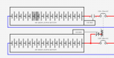
Below is a wiring schematic of how I am intending on wiring things up, and rendering of how I am thinking I will layout the components. I appreciate any comments/suggestions others may have to offer. This is my first time working with an "all in one" inverter or LiFePO4 battery. I still need to decide on which BMS to purchase, and welcome recommendations...


After reading lots of post on this forum decided to pursue an "all in one" inverter design with a LiFePO4 battery bank. Ordered 32 EVE 280ah cells on Alibaba from Amy at Xuba. Placed order, paid by wire to avoid the credit card hassles others have posted about and 3 days later the cells were shipped and on there way.
For the inverter decided to go with 2 Growatt SPF3000TL LVM 48 (3000W-48V) inverters. I had also considered the MPP Solar inverters but decided to go with Growatt because of brand (Growatt; top 10 PV inverter manufacturer), and with Growatt the parallel card/cables were included as was a wifi dongle and remote monitoring software. I purchased the inverters from Ian at https://watts247.com . Ian answered a ton of my questions, had the inverters in stock, shipped the same day and I had them 3 days later. Could not be easier.
2 x SPF3000 in parallel allows me to have up to 9kw of PV input (160A) and 6000Wac output at either 120 or 120/240Vac. I don't see needing 6000W output capacity often so intend to operate just one of the inverters , keeping the other in backup most of the time. I intend to have ~5.5kW peak of solar and will split the array output with 1/2 going to each inverter (My understanding is the inverters built in MPPT charger operates even if the inverter is turned off).
Below is a wiring schematic of how I am intending on wiring things up, and rendering of how I am thinking I will layout the components. I appreciate any comments/suggestions others may have to offer. This is my first time working with an "all in one" inverter or LiFePO4 battery. I still need to decide on which BMS to purchase, and welcome recommendations...
")