Today I got to the last step of commissioning my SunnyBoy SB3.6-1AV-41 (3.6kW inverter). Looking at the documents I see two PDFs with similar content, but with one major difference regarding the "normal" PV array connection.
I have a single string of 6 535W Jinko PVs. Open voltage reads about 265V IIRC. Two 4mm2 cables are to be connected to the inverter. The question is how...
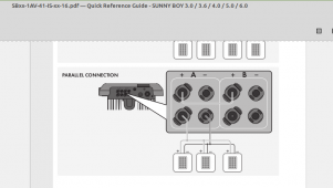
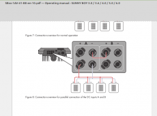
Here are the two pictures with the major difference in the "normal" connection (check the upper wire). I would appreciate if somebody with a SunnyBoy in normal PV connection mode can take a picture of the PV connection wires at the inverter.


The black and white image is from the Quick Reference Guide for SBxx-1AV-41-IS-xx-16 | VerSBxx-1AV-41-BE-en-10 | Version 1.0sion 1.6
The color image is from Operation Manual for SBxx-1AV-41-BE-en-10 | Version 1.0
On the official SMA site, I see the black and white version currently.
I have a single string of 6 535W Jinko PVs. Open voltage reads about 265V IIRC. Two 4mm2 cables are to be connected to the inverter. The question is how...
Here are the two pictures with the major difference in the "normal" connection (check the upper wire). I would appreciate if somebody with a SunnyBoy in normal PV connection mode can take a picture of the PV connection wires at the inverter.


The black and white image is from the Quick Reference Guide for SBxx-1AV-41-IS-xx-16 | VerSBxx-1AV-41-BE-en-10 | Version 1.0sion 1.6
The color image is from Operation Manual for SBxx-1AV-41-BE-en-10 | Version 1.0
On the official SMA site, I see the black and white version currently.
Last edited:


