diy solar

diy solar

Smaller 800W Off-Grid Solar Panel System Arrangement

Peets

New Member
Joined
Feb 24, 2023
Messages
5
Location
Hungary
I'm planning to setup a smaller 800W off-grid solar panel system for my weekend cottage in Western Europe.

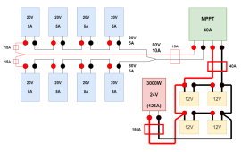
I already bought the necessary parts, cables, and accessories, here's my design sketch for this off-grid solar panel system:
solar.png

Parts:​

  • Batteries: 4x 120Ah 12V BIG Professional Solar DC
  • Solar Panels: 8x 100W 12V Renogy Monocrystalline (compact design version)
  • Charge Controller: EPEVER Triron 4215N 40A 150V MPPT 12/24VDC + EPEVER MT50 Remote Control
  • Inverter: Novopal 3000W 24V Pure Sine Voltage Converter
  • 1x 150A ANL Fuse (between the battery bank and the inverter)
  • 2x 15A Inline Solar Panel Fuse (for the 2 clusters of 400W solar panels)
  • 1x 15A 500V DC Curcuit Breaker (between the solar panels and the charge controller)
  • 1x 40A 500V DC Curcuit Breaker (between the charge controller and the battery bank)
  • necessary Y plugs, 2x 10m of standard 10AWG (6mm2) solar cable extension cords and thick 3/0AWG (95mm2) cables for the batteries and the inverter

Short Plan Summary:​

  • 1.: connect the 4 batteries in series AND parallel getting 24V of 240Ah
  • 2.: connect this battery bank with the 3000W 24V inverter, there's a 150A ANL fuse between the inverter and the battery bank
  • 3.: connect the EPEVER charge controller with the battery bank, there's a 40A 500V DC circuit breaker between them
  • 4.: create 2 clusters of 400W solar panels in series (20V 5A => 80V 5A), then connect these 2 clusters with 15A inline fuses, thus getting the 800W solar panel array (2x 80V 5A => 80V 10A) - the EPEVER charge controller can handle only 150V Max PV
  • 5.: connect the solar panel array to the charge controller, there's a 15A 500V DC circuit breaker between the solar array and the charge controller

Questions:​

  • 1.: As the EPEVER charge controller can handle only 150V Max PV, the solar panel array consists of 2 clusters of 400W solar panels in series, then connect them in parallel. Is this a correct way to connect these 8x 100W solar panels to my EPEVER charge controller in my case?
  • 2.: Are the 15A inline fuses, the 15A, and 40A circuit breakers, and also the 150A ANL fuse correct/applicable for this system?
  • 3.: When the solar system is fully connected, is there a recommendation for where to connect the inverter to the battery bank to? Connect closest to the charge controller (i.e.: connect the inverter cable directly to the battery tab/terminal/bushing where the charge controller connected too), or farthest from the charge controller connection (i.e.: connect the inverter cable essentially the opposite/farthest battery tabs/terminals/bushings)
Any corrections, suggestions, and help is highly appreciated.
 
Is this a correct way to connect these 8x 100W solar panels to my EPEVER charge controller in my case?
This looks to me like a good way to do it.

is there a recommendation for where to connect the inverter to the battery bank to
Yes there is a correct way to do it. You want to go to opposite sides of the battery bank. What you have in your diagram is not quite right. Same goes for the the charge controller. You want it to go to opposite sides of the battery bank.

Right now as you have it the top 2x 12v batteries in series would charge faster and the bottom 2 would discharge faster.

I don’t know much about this website I’m sharing, I just did a quick search, but it describes what I’m talking about.

I would read the whole thing, but what I’m talking about is in the section titled: Combined Series/Parallel Battery Connections

 
Last edited:
  • 1.: As the EPEVER charge controller can handle only 150V Max PV, the solar panel array consists of 2 clusters of 400W solar panels in series, then connect them in parallel. Is this a correct way to connect these 8x 100W solar panels to my EPEVER charge controller in my case?
Yes. And I would probably orient the two series arrays SE (or SSE) and SW to potentially get a bit more charge earlier in the sun day and later in the day. That is a situation that has worked well for my 800W system.
  • 2.: Are the 15A inline fuses, the 15A, and 40A circuit breakers, and also the 150A ANL fuse correct/applicable for this system?
If lithium batteries a Class T would be preferable due to the potential for 10kA output in some unforeseen bad situation.
  • 3.: When the solar system is fully connected, is there a recommendation for where to connect the inverter to the battery bank to? Connect closest to the charge controller (i.e.: connect the inverter cable directly to the battery tab/terminal/bushing where the charge controller connected too), or farthest from the charge controller connection (i.e.: connect the inverter cable essentially the opposite/farthest battery tabs/terminals/bushings)
Someone covered that above.

You may not prefer this idea, but with a 3000W inverter if you are never going to expand or scale up your system and if you wish to incorporate RV/automotive device chargers, lighting, water pump, etc. i would for myself choose 12V batteries and inverter. 2000- or 2500W is a typical maximum you really want to do with 12V batteries, but you can stretch to 3000W without major concern.

If your loads are not typically going to be above 1500-2000W sustained (and I’d guess for a system that size they won’t be) then you could do this IF the 12VDC could be useful to you. The cable cost will be the same for the description you gave, still be safe, and let you use some commodity DC items, but you’d need higher amp fuses for the 4/0
If your only loads are going to be (assuming 240VAC) 240VAC items there is no reason to use 12V other than 12V inverters are more likely to be sourced locally, and in some emergency situation you could potentially use your gasoline/diesel automobile to charge the batteries.

Just thought I would throw that out there but don’t stress over it- it’s just an option you might consider but may not be appealing or useful to you.
 
This looks to me like a good way to do it.


Yes there is a correct way to do it. You want to go to opposite sides of the battery bank. What you have in your diagram is not quite right. Same goes for the the charge controller. You want it to go to opposite sides of the battery bank.

Right now as you have it the top 2x 12v batteries in series would charge faster and the bottom 2 would discharge faster.

I don’t know much about this website I’m sharing, I just did a quick search, but it describes what I’m talking about.

I would read the whole thing, but what I’m talking about is in the section titled: Combined Series/Parallel Battery Connections


Thank you for your post, I found the article useful!
 
Nice diagram btw. What type of batteries?

Thanks! 4x 120Ah C100 German-made entry level, good quality SLA deep-cycle batteries (link). Based on posts on other forums and in my personal circle, If I keep these batteries above 50% SOC, their expected lifetime will be between 3 and 5 years.
 
Yes. And I would probably orient the two series arrays SE (or SSE) and SW to potentially get a bit more charge earlier in the sun day and later in the day. That is a situation that has worked well for my 800W system.

If lithium batteries a Class T would be preferable due to the potential for 10kA output in some unforeseen bad situation.

Someone covered that above.

You may not prefer this idea, but with a 3000W inverter if you are never going to expand or scale up your system and if you wish to incorporate RV/automotive device chargers, lighting, water pump, etc. i would for myself choose 12V batteries and inverter. 2000- or 2500W is a typical maximum you really want to do with 12V batteries, but you can stretch to 3000W without major concern.

If your loads are not typically going to be above 1500-2000W sustained (and I’d guess for a system that size they won’t be) then you could do this IF the 12VDC could be useful to you. The cable cost will be the same for the description you gave, still be safe, and let you use some commodity DC items, but you’d need higher amp fuses for the 4/0
If your only loads are going to be (assuming 240VAC) 240VAC items there is no reason to use 12V other than 12V inverters are more likely to be sourced locally, and in some emergency situation you could potentially use your gasoline/diesel automobile to charge the batteries.

Just thought I would throw that out there but don’t stress over it- it’s just an option you might consider but may not be appealing or useful to you.

Thank you for your detailed insights, I found them really helpful!

So far your are right, my loads are typically under ~1500W (I have a power consumption monitoring socket).

I was hesitant about the size of the inverter and maybe in the future I will change it based on my updated needs. As of now a 2000W inverter would be surely enough for most of my use cases, I rarely go above 1400W-1500W on my days. But sometimes when I make an espresso or print something with my laser printer, the 3000W can still be larger, than needed, but I oversized a bit for safety reasons and for these rare higher power loads.

Have a great day!
 

diy solar

diy solar
Back
Top