RV Jim
Newbie needing help
Hello everyone and a thank you for the awesome advice I am going to receive. Here's my question(s)
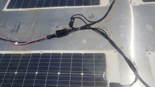
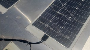
1. I have 4 panels on the roof of a cargo trailer I purchased and decided to check the voltage output. Much to my surprise I got 36.4 ...I'm confused about that number. Do I have a dead panel ?
2. What should 1 panel have for voltage...12v ?
3. I plan to purchase a Lifepo4 battery(12v) to supply charging power for phone or other small devices so do I need to rewire the panels for 12v output ?
5. Sorry for the ignorance of the correct terms as I confuse series and parallel...one should give 12vdc output and the other 48vdc out I think.